OPERATOR’S MANUAL
EDGE QUALIFIED TRIGGER SETUP
1. Touch the Trigger descriptor label.
2. Touch the Qualified trigger button.
3. Under "Arm trigger on Event 'A'" select Edge as the condition on which to arm the trigger. The Edge condition
will automatically be selected under "Then trigger on Event 'B'" also.
4. Under "When 'B' occurs", select a wait condition (time or events) and set a value.
5. Touch the Event 'A' Edge tab.
6. Select a trigger source under "Qualifier Setup."
7. Set a trigger voltage level in the Level field. Then select a slope and coupling.
8. Touch the Event 'B' Edge tab and make the same setups for the dependent trigger.
Pattern (Logic) Trigger
HOW LOGIC TRIGGER WORKS
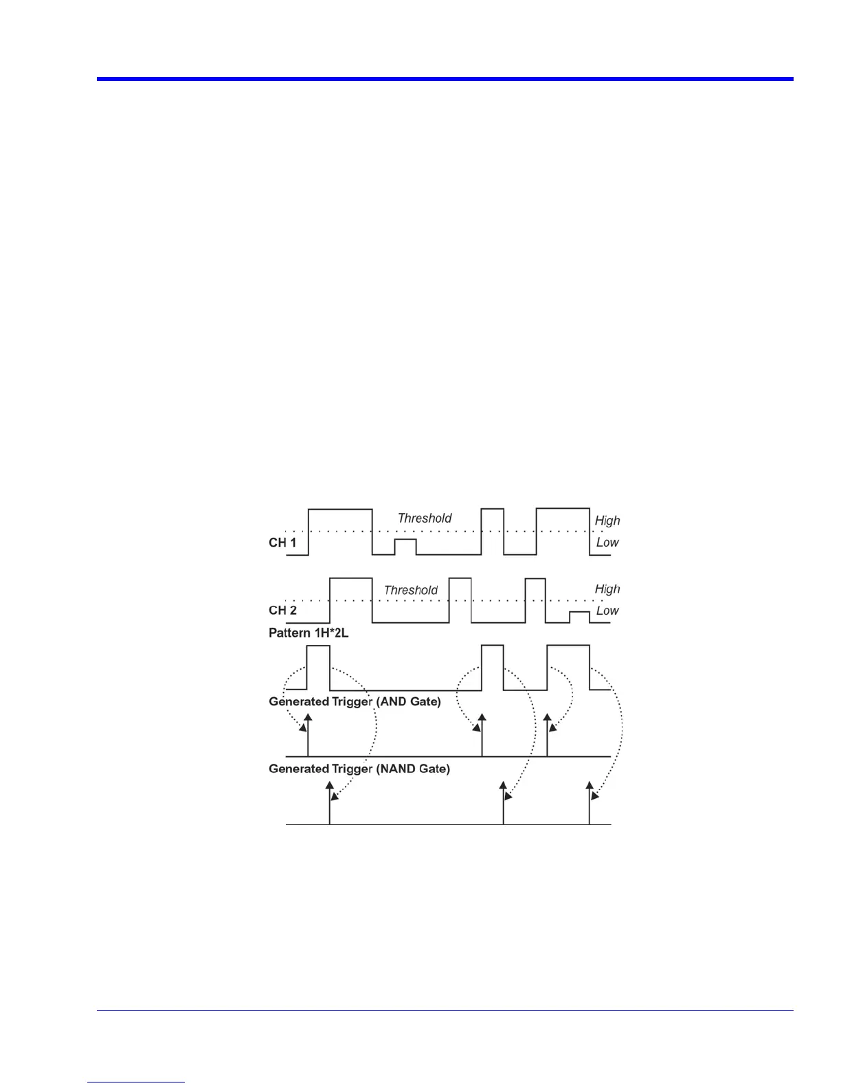
Logic Trigger enables triggering on a logical combination of up to five inputs: CH 1, CH 2, CH 3, CH 4, and EXT.
The combination of inputs is referred to as a pattern. There are four logic gates available: AND, NAND, OR, NOR.
A trigger state is either high or low: high when a trigger source is greater than the trigger level (threshold) and low
when less than it. For example, an AND pattern could be defined as true when the trigger state for CH 1 is high,
CH 2 is low, and EXT is irrelevant (X or don't care). If any one of these conditions is not met, the pattern state is
considered false.
Logic Applications
Logic Trigger can be used in digital design for the testing of complex logic inputs or data transmission buses.
L
OGIC TRIGGER SETUP
1. Touch the Trigger descriptor label.
2. In the Trigger dialog, touch the Pattern trigger button.
3. If you want to hold off the trigger (either in time or events) when the pattern becomes true, touch one of the
Holdoff By: buttons. Then touch inside the holdoff data entry field and enter a value, using the pop-up
keypad.
WRXi-OM-E Rev C 65