2: Description of the system
19
GNSS Reference Station Components
GNSS Reference Station Components
Component overview
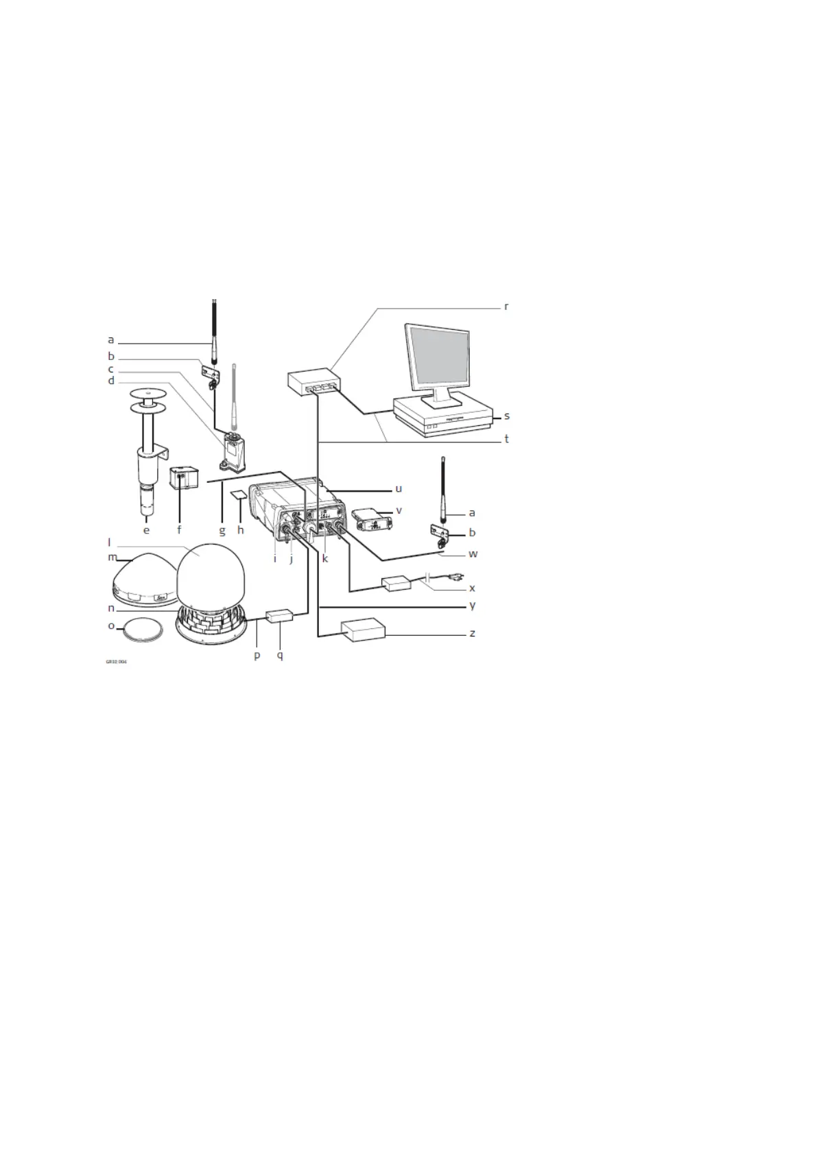
The following diagram shows a typical reference station setup and the most common accessories that can be used with a
GR10/GR25/GM10.
b. Antenna bracket
c. Antenna cable
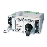
d. GFU housing including
Radio/GSM device
e. Meteo sensor
f. Tilt sensor
g. Serial cable
h. SD card
i. Bluetooth or WLAN
antenna *
j. Serial port 2 / Event port *
k. Connector for external
oscillator
l. Optional radome for AR25
m. GNSS antenna, AR10
n. GNSS antenna, AR25
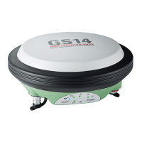
o. GNSS antenna, AS10
p. Antenna cable
q. Optional lighting protection
r. Ethernet hub
s. Computer running GNSS
Spider or Web interface
t. Ethernet cable
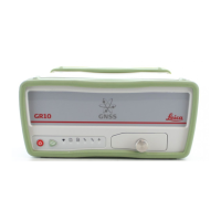
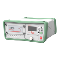
u. GR10/GR25/GM10
v. Slot-in radio/GSM device
w. Antenna cable
x. Power supply
y. PPS cable *
z. Device receiving electric
pulse *
* GR25 only
 Loading...