8400 StateLine C | Reference manual
Motor control (MCTRL)
V/f characteristic control (VFCplus)
140 L Firmware ≤ 11.00 - DMS 8.0 EN - 10/2011
5.4.3.6 Defining a user-defined V/f characteristic
This function extension is only available from version 04.00.00!
For individual adaptation of the motor magnetisation to the actual application, the motor
control "10: VFCplus: V/f definable" with a freely definable characteristic can be selected in
C00006
as an alternative if the linear and quadratic characteristics are not suitable.
The 11 grid points (voltage/frequency values) of the characteristic are stipulated by
means of the 11 subcodes of C00967
and C00968.
– It is necessary to set all 11 grid points by means of corresponding subcodes.
– If fewer grid points (voltage/frequency values) are needed, this can be achieved
indirectly by ascribing the same voltage and frequency values to consecutive grid
points.
Example: C00967/3 = C00967/4 and C00968/3 = C00968/4
– The grid points can be specified in any sequence. Internally, they are automatically
ordered from the minimum to the maximum frequency value.
– Above the maximum and below the minimum frequency, the previous rise is
continued until the maximum output voltage.
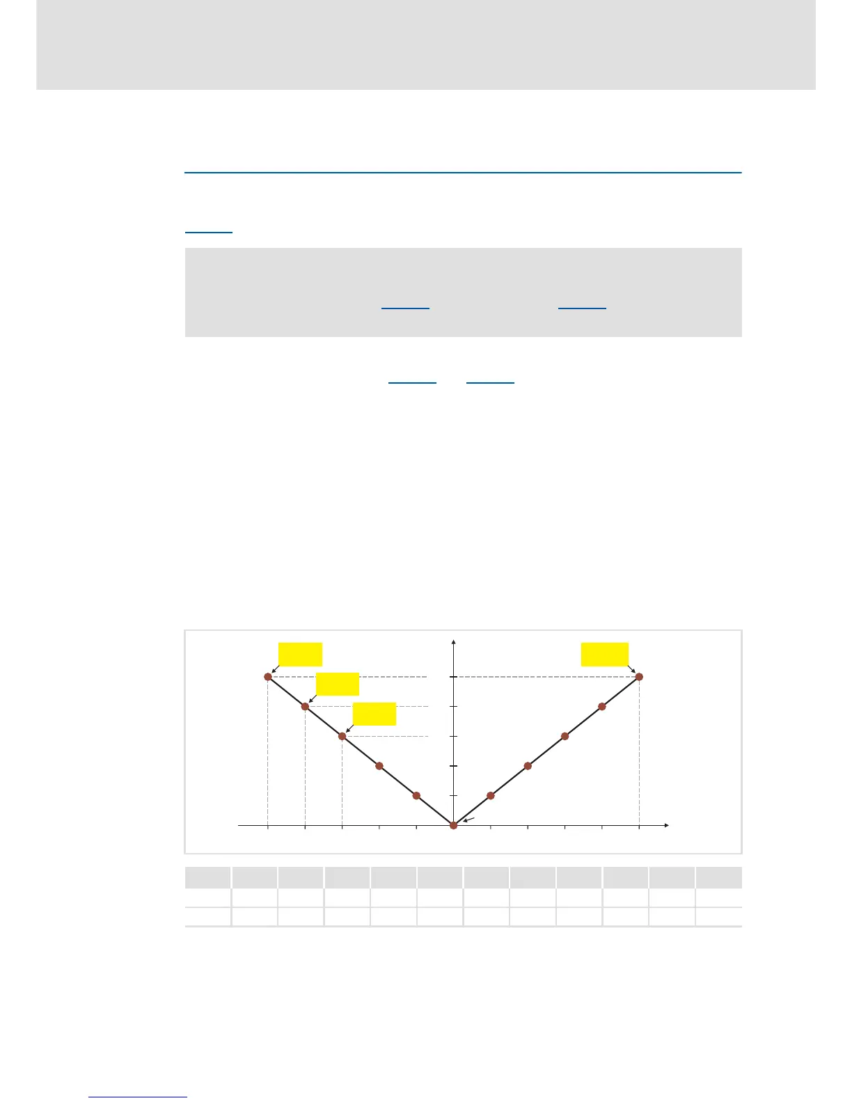
In the Lenze setting, the 11 grid points represent a linear characteristic.
– 3-phase devices: Output voltage 400 V at f = 50 Hz
– 1-phase devices: Output voltage 230 V at f = 50 Hz
[5-7] Freely definable characteristic (Lenze setting for 3-phase devices)
Note!
The V/f base frequency (C00015) and the V
min
boost (C00016) no longer exert an
influence if this motor control is chosen.
P1 P2 P3 P4 P5 P6 P7 P8 P9 P10 P11
V 400 V 320 V 240 V 160 V 80 V 0 V 80 V 160 V 240 V 320 V 400 V
f -50 Hz -40 Hz -30 Hz -20 Hz -10 Hz 0 Hz 10 Hz 20 Hz 30 Hz 40 Hz 50 Hz

 Loading...