Firmware ≤ 11.00 - DMS 8.0 EN - 10/2011 L 63
8400 StateLine C | Reference manual
Commissioning
Commissioning of the "Switch-off positioning" technology application
3.7.1 Prepare controller for commissioning
1. Power connection wiring
– Refer to the mounting instructions supplied with the drive controller to find help on
how to correctly design the power connections to match the requirements of your
device.
2. Wire the control connections
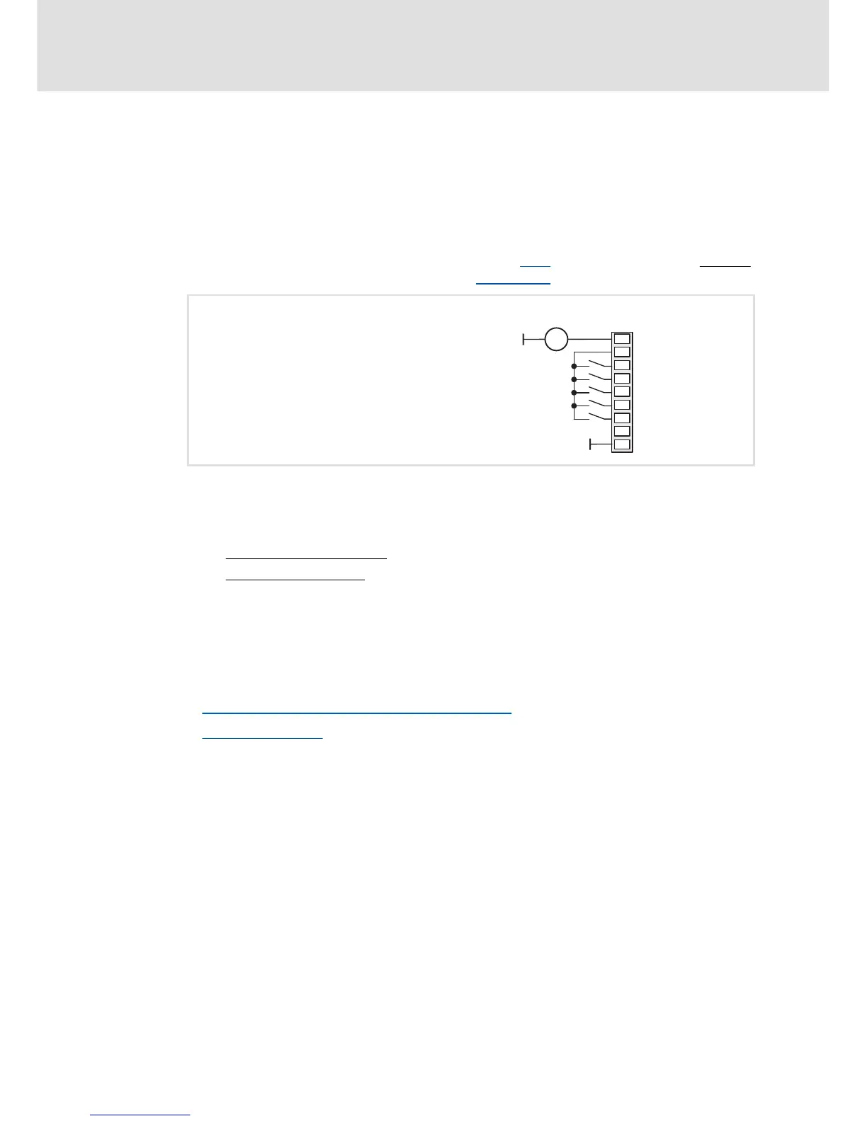
– In case of the application shown in illustration [3-2]
, switch-off positioning without
pre-switch off, wiring according to the "Terminals 2
" control mode makes sense:
3. Inhibit controller: Set terminal X4/RFR to LOW level or open contact.
4. Connect USB diagnostic adapter.
5. Switch on voltage supply of the controller.
– Without motor operation
: Connect external 24 V supply.
– With motor operation
: Connect mains voltage.
If the green "DRV-RDY" LED is blinking and the red "DRV-ERR" LED is off, the controller is
ready for operation and commissioning can proceed.
Related topics:
Automatic restart after mains connection/fault...
( 97)
LED status displays
( 381)
DI3
DI2
DI4
DO1
GIO
24I
DI1
RFR
24E
+
=
X4
Controller enable / reset error
Stop function 1
Stop function 2
CW rotat. quick stop / selection: switch-off pos. 1
CCW rotat. quick stop / selection: switch-off pos. 2
External 24 V DC
supply