Firmware ≤ 11.00 - DMS 8.0 EN - 10/2011 L 53
8400 StateLine C | Reference manual
Commissioning
Commissioning of the "Actuating drive speed" technology application
3.6 Commissioning of the "Actuating drive speed" technology application
System constellation
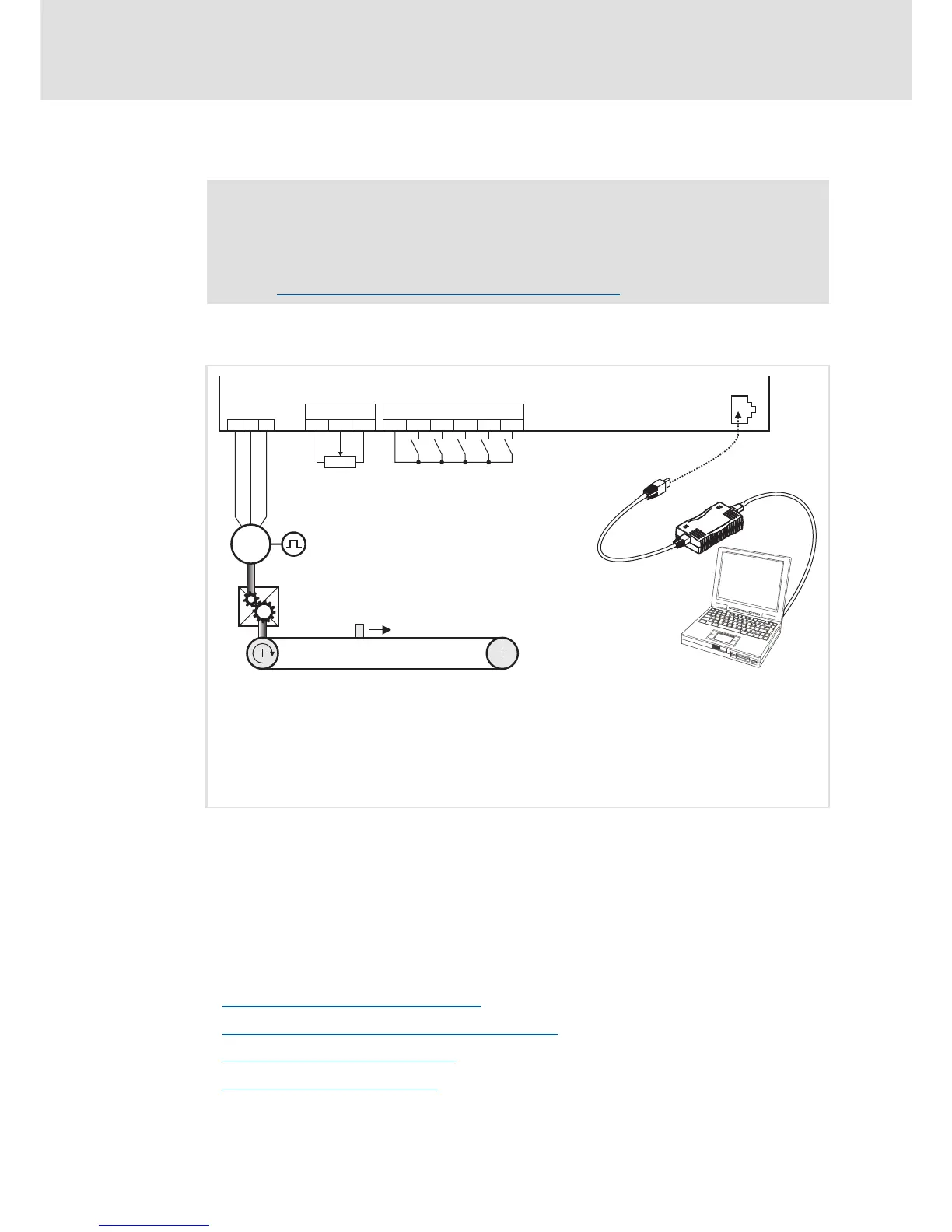
[3-1] Block diagram for wiring the commissioning example for the "Actuating drive speed" application
Commissioning steps
Find a description of the commissioning steps of the "Actuating drive speed" technology
application below.
Please observe the sequence of the steps in the following chapters and follow them
through carefully. This will help you to commission your controller quickly and as safely as
possible:
Prepare controller for commissioning
( 54)
Creating an »Engineer« project and going online
( 55)
Parameterising the motor control
( 56)
Parameterising the application
( 57)
Note!
Take all the necessary safety precautions before you carry out the following
commissioning steps and switch the device on!
Safety instructions with regard to commissioning
( 48)
X3/AR Reference voltage (10 V) for analog signals
X3/A1U Speed setpoint selection (slider of setpoint potentiometer R)
• Scaling: 10 V ≡ 100 % ≡ 1500 rpm
1
(for a 4-pole motor)
X3/GA Ground potential (GND) for analog signals
X4/RFR Controller enable
X6 Diagnostic interface for connecting the USB diagnostic adapter

 Loading...