Page 26 / 119 Section 4. TPS matrix concept
4.4.2. Serial interface
Technical background
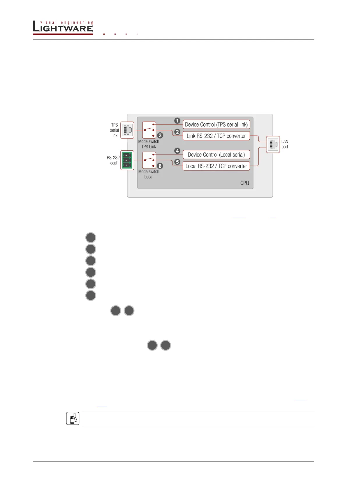
Serial data communication can be established via the local RS-232 port (Phoenix
connector) or via the TPS lines. The RS-232 ports – which are connected to the
microcontroller – can be configured separately (e.g. if the Baud rates are different, the
microcontroller does the conversion automatically between the ports). The RS-232 port can
be switched to Control mode, Command Injection mode, or can be Disconnected; see the
figure below.
Figure 4-8. The block diagram of the Serial interface
All settings are available in the LDC software, see section 6.7.1 on page 56.
The following settings are defined:
The TPS serial link port is in Control mode.
The TPS serial link port is in Command Injection mode.
The TPS serial link port is Disconnected.
The Local serial port is in Control mode.
The Local serial port is in Command Injection mode.
The Local serial port is Disconnected.
Control mode
The incoming data from the given port is processed and interpreted by the Microcontroller.
The mode allows to control the matrix directly. LW2 or LW3 protocol commands are
accepted – depending on the current port setting.
Command injection mode
In this mode, the matrix works as an RS-232–Ethernet bidirectional converter. The Ethernet
packets are converted to RS-232 data and vice versa. Unique TCP/IP port numbers are
defined for the serial ports (TPS and local) for this purpose. E.g. the default Command
Injection port number of the local RS-232 port is 8001. If a command is coming from the
LAN interface which is address to the port no. 8001, it will be transmitted to the Tx pin of
the local RS-232 port. That works in the opposite direction of course and the method is the
same on the serial interface of the TPS ports. See the RS-232 settings of section 10.6 on
page 116.
ATTENTION!
The serial data cannot be routed from an RS-232 port to another RS-232 port.
 Loading...