Page 50 / 119 Section 6. Software control – Using Lightware Device Controller
6.4.7. Cable diagnostics (TPSIN, TPSOUT)
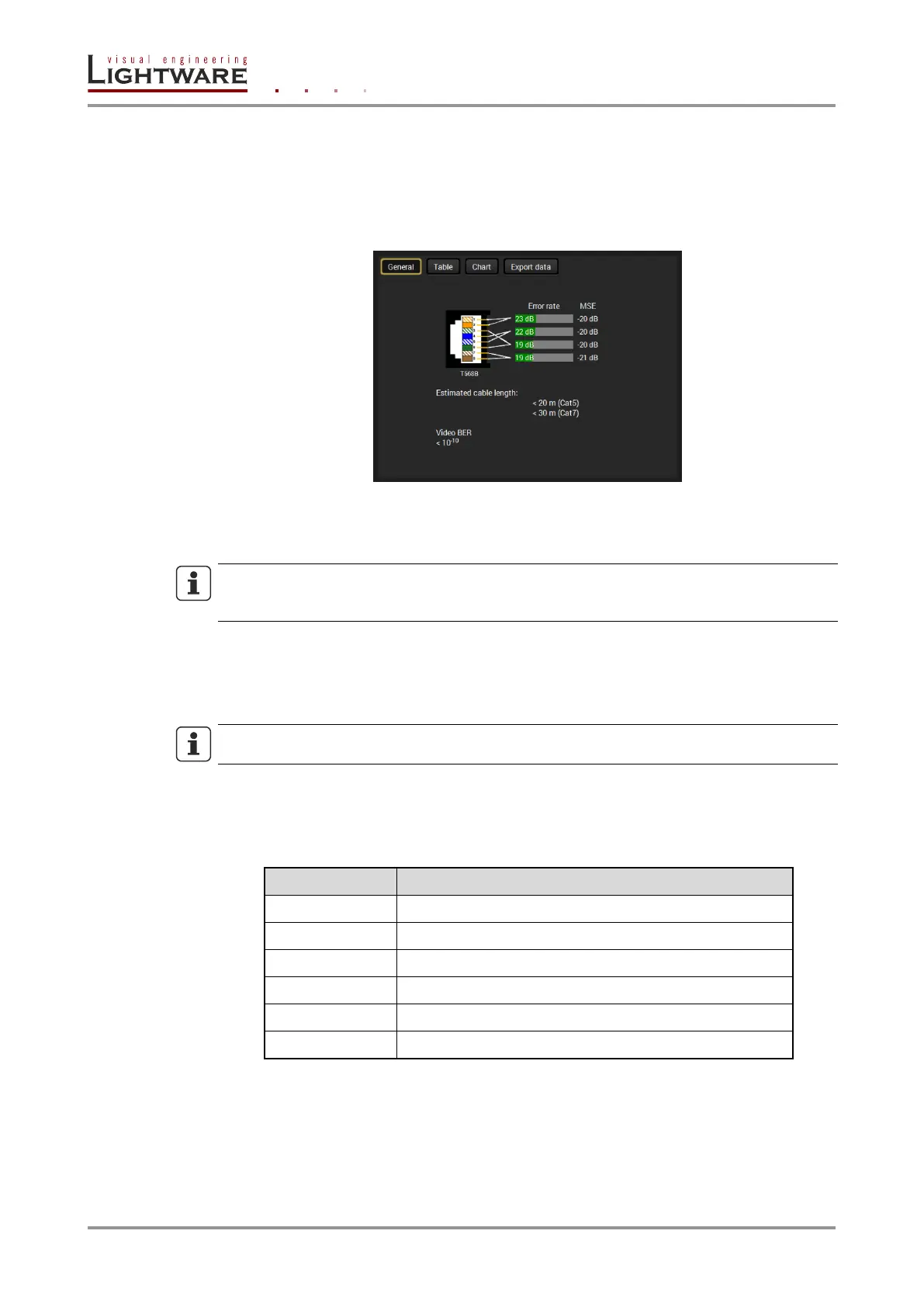
The estimated cable length and the quality of the link are measured periodically and the
diagnostic window shows the values in real-time. If the green bars hit the first line in the
middle they turn into red. It means the number of the errors – during the extension – is
higher than the recommended one. The link might be alive but recovering of the received
data is not guaranteed.
Figure 6-4. TPS cable diagnostics window
Each bar represents a differential line in the CATx cable. The inappropriate termination of
the cable usually occurs high error rates. Check the cable terminations or change the cable.
INFO
The estimated length is valid for a Cat5e AWG24 cables. Cat7 cable length is calculated
from the measurement of a Cat5e AWG24 cable.
Table and chart
The parameters are measured in every second and the values can be seen in a table or
on a chart by clicking the button. The listed values can be downloaded as a CSV file
(Comma Separated Values).
INFO
The data is measured and collected only when the Cable diagnostics window is opened.
Video BER (Bit Error Ratio)
This feature works in conjunction with the TPS receiver’s side and is about to show the
average bit error numbers in the transmitted video signal. The value is displayed only if the
installed firmware on the RX side supports this feature. Reference values:
Minor error, not recognizable by eyes
Sometimes recognizable flash on a special test pattern
Easy to recognize image error
Table 6-3. Bit Error Ratio (BER) classification
Above displayed “Video BER < 10
-10
” value means there is 1 bad pixel after 10
10
pixels on
average, which means the number of the bit errors is about 1 pixel in every 80 seconds
when the transmitted signal is 1920x1080p @ 60 Hz.
 Loading...