1-88
ENGINE <TURBO>
-
Acceleration System
ACCELERATION
SYSTEM
N71
BWOOAA
ACCELERATOR PEDAL AND ACCELERATOR CABLE
The accelerator pedal and accelerator cable are
the same as used on 420A engine. (Refer to
P.l-62)
AUTO-CRUISE CONTROL SYSTEM
By using the auto-cruise control, the driver can drive
at the speed he likes [in a range of approximately
40 to 200 km/h (25 to 124 mph)] without depressing
the accelerator pedal.
CONTROL SYSTEM
The throttle position sensor signal is used in addition
to the conventional vehicle speed sensor as the
input signal to bring about the following improve-
ments in control.
(1)
The amount of actuator control varies according
to vehicle speed and throttle opening not only
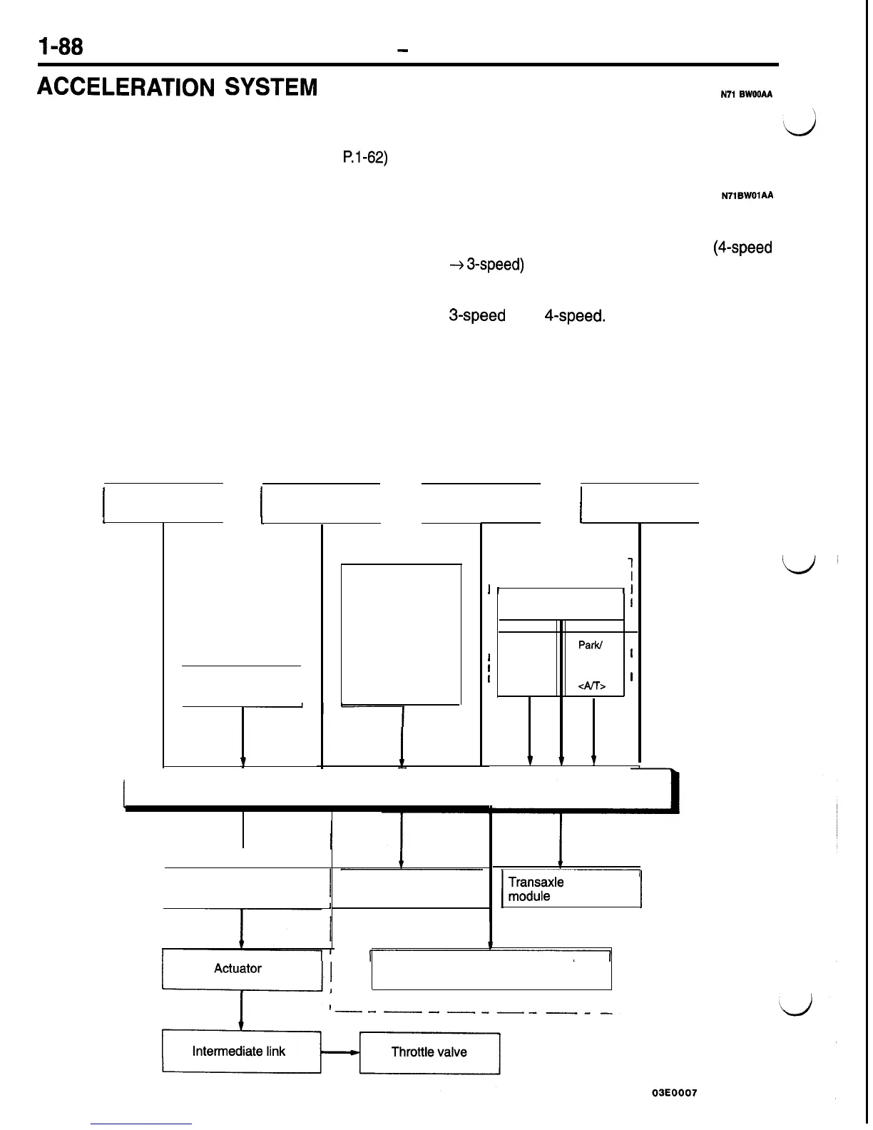
System Block Diagram
<Control system>
I
I
Main switch
I
I
Throttle position
sensor
1
I
I
Closed throttle
position switch
N71BWOlM
for an expansion of conformity to differences
in engine output but also for better response.
(2) On A/T models, overdrive is released
(4-speed
+
3-speed)
when climbing inclines and the sys-
tem judges the return time by vehicle speed
and throttle opening to prevent hunting between
3-speed
and
4-speed.
ACTUATOR SYSTEM
The actuator system consists of the motor-driven
vacuum pump, actuator and intermediate link. The
vacuum pump and actuator are in different locations.
Vehicle speed
sensor
I
I
OD switch
I
I
I
Control switch
l
SET switch
l
RESUME
switch
l
CANCEL
switch
1
Control unit
--------------
<Actuator system>
I
Vacuum pump assembly
Diagnostic output
terminal
r----
-------
I
Cancel system
:
I
I
I
I
I
Stop light switch
i
I
I
I
I
I
I Clutch
Park/
I
1
pedal
Neutral
1
1
position
position I
1
switch
switch
1
, <M/T>
<A!T>
I
L---------.---J
1
1
1
1
TmTr;Ele
control
j
Auto-cruise control indicator light
(in combination meter)

 Loading...


