6-26
INTERIOR
-
Supplemental Restraint System (SRS)
19X0485
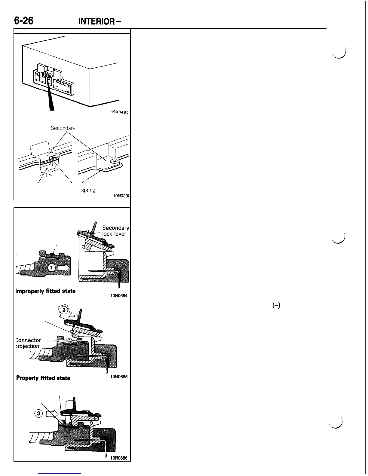
UNLOCKED
LOCKED
Secondarv lock lever
Connecter
notch
Lock
sprmg
19N029(
Harness side
connector
Primary lock
/
Improperly
fitted
state
Forced down
SRS diagnostic
unit side connector
Secondary
lock lever
projection
lonnector
-
xojection
,-
Properly
fitted
state
13R0685
Lock spring
Primary lock
!'
13R068E
SRS CONNECTOR
The connector of the SRS diagnostic unit has a double lock
mechanism, fit verification mechanism and connector shorting
mechanism.
a
DOUBLE LOCK MECHANISM
The mechanism is composed of two mechanisms: each connec-
tor of the SRS diagnostic unit is locked to the connector of
the harness, then these connectors (of the four harnesses)
are locked with the secondary lock lever mounted on the con-
nector of the SRS diagnostic unit side.
The secondary lock lever locking is done as the lock spring
fits in the notch of the connector. The operating principle is
described below.
When Connectors are to be Fitted
(1) The SRS diagnostic unit and harness side connectors are
fitted. (Primary lock)
(2) The secondary lock lever mounted to the SRS diagnostic
unit side connector is pressed down by finger until a click
’
vj
is heard indicating that the connectors have been locked.
(Secondary lock)
If the harness and SRS diagnostic unit connectors do not
properly fit, the secondary lock lever side projection and
the harness side connector projection interfere with each
other, making it impossible to lock the connectors.
When Connectors are Unlocked
(1) Press in the lock spring with a flat tip
(-)
screwdriver to
disengage the lock spring from the notch area of the connec-
tor, and release the lock (secondary lock) of the secondary
lock lever.
Caution
Forced removal of the connector without releasing
the secondary lock lever will result in a damaged lock
lever.
(2)
Press the primary lock of each of the harness side connec-
tors and remove the harness side connector.

 Loading...


