6-22
INTERIOR
-
SuDdemental
Restraint System
(SRSI
SRS DIAGNOSTIC UNIT
The SRS diagnostic unit monitors the impact
sen-
sors, squib, wiring harness, condensers, battery
volt-
age etc. If it detects a problem, it illuminates the
“SRS” warning light to alert the driver. It also stores
in memory what the problem is, and the duration
of the problem (the duration during which the
warn-
ing light stayed ON).
The condensers provided in the diagnostic unit
accu-
mulate
electric energy during the period the ignition
switch is ON. This supplies squib ignition current,
even if the power cable from the battery is broken
by the collision, to inflate the air bag as soon as
‘d
the front impact sensor and safing impact sensor
are simultaneously switched ON.
Caution
Make sure that the SRS diagnostic unit is never
disassembled.
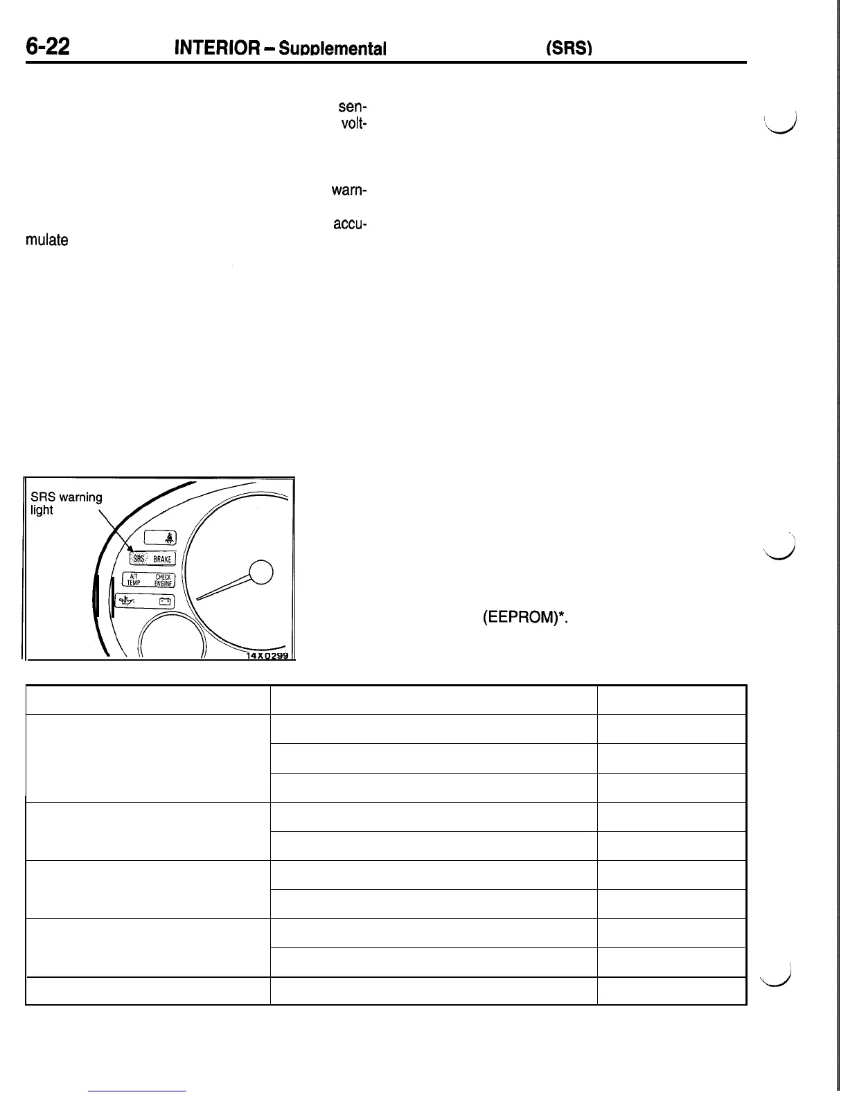
1. Monitoring function
The SRS diagnostic unit monitors the wiring harness and SRS
components shown in the following table to check whether
they satisfy the specified values. When the ignition key is in
“ON” or “START” position, the SRS warning light should illumi-
nate for about 7 seconds and then turn off.
This indicates that the SRS system is in operational order.
If the SRS warning light does any of the following, immediate
inspection is needed.
(1) The SRS warning light does not illuminate as described
above.
\\
(2) The SRS warning light stays on for more than 7 seconds.
d
(3) The SRS warning light illuminates while driving.
The fault data is stored in terms of a diagnostic code in the
non-volatile memory
(EEPROM)*.
The duration of the fault
is also stored in terms of the ON duration of the warning light.
Component
Front impact sensor
Air
bag module (Driver’s side)
Air bag module (Passenger’s side)
Condenser
Cranking detection circuit
Main Monitoring
Point
Short circuit
Open-circuit once
Open-circuit twice
Short circuit
Open circuit
Short circuit
Open circuit
Terminal voltage high
Terminal voltage low
Cranking signal detection
time
Diagnostic Code No.
11
12
13
21
22
24
25
31
32
33”
a

 Loading...


