INTERIOR
-
Seat
6-7
Worm
aear
B
Slide
adjustment
switcl
-.-----a---
Limit
.ywq
Lower rail
-
Cable wire
19X0668
POWER
SEAT
Slide Adjustment Structure
N76ZDOlAA
The motor, limit switch and gears are mounted on the plate
fixed to the lower rails.
When the slide adjustment switch is operated, the motor starts
and rotates worm gear A in the gear box via the cable wire.
This rotating torque is transmitted through gears A and B to
worm gear B. The worm gear B moves the upper rails and
therefore the seat mounted on the upper rails.
When the seat slides to the forward or backward limit, the
cover mounted to the upper rail pushes the limit switch and
turns the motor off. This stops the seat slide operation.
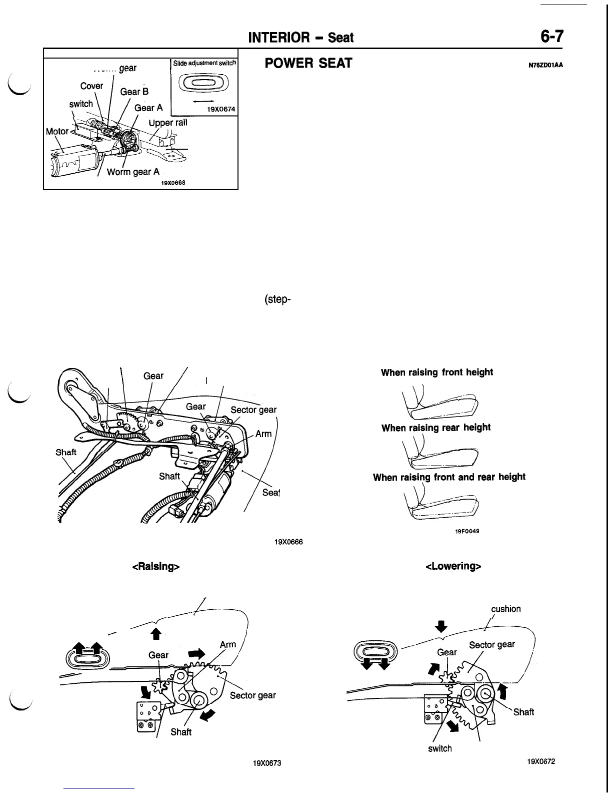
Front Height and Rear Height Adjusting Structure
The front and rear portions of the seat cushion can
be raised and lowered independently. If the front
height and rear height switch is pushed to the up
side, motor revolutions will be transferred to gear
to sector gear. Since the sector gear, shaft and arm
are fixed, the seat cushion rises continuously
(step-
less) along with the revolution of the sector gear.
Sector gear
Rear height motor
a
Arm
\
Front height motor
:
cushion
As the seat cushion continues to rise, the claw on
the shaft turns the limit switch from ON to OFF,
cutting off power to the motor and stopping it.
In addition, if the front height and rear height switch
is pushed to the down side, operation is reversed
with the motor revolving in the opposite direction
and lowering the seat cushion.
When
raising
front
height
When
raising
rear
height
/!&.=I
When
raisiyg
front
and
rear
height
19FOO49
<Raising>
<Lowering>
Seat cushion
/
Power seat switch
‘+“.
,.f-----.
,
Limit switch
19X0673
Seat
yshion
Power seat switch
Limit
switch
Arm

 Loading...


