EQUIPMENT
-
ETACS
L
/
L/
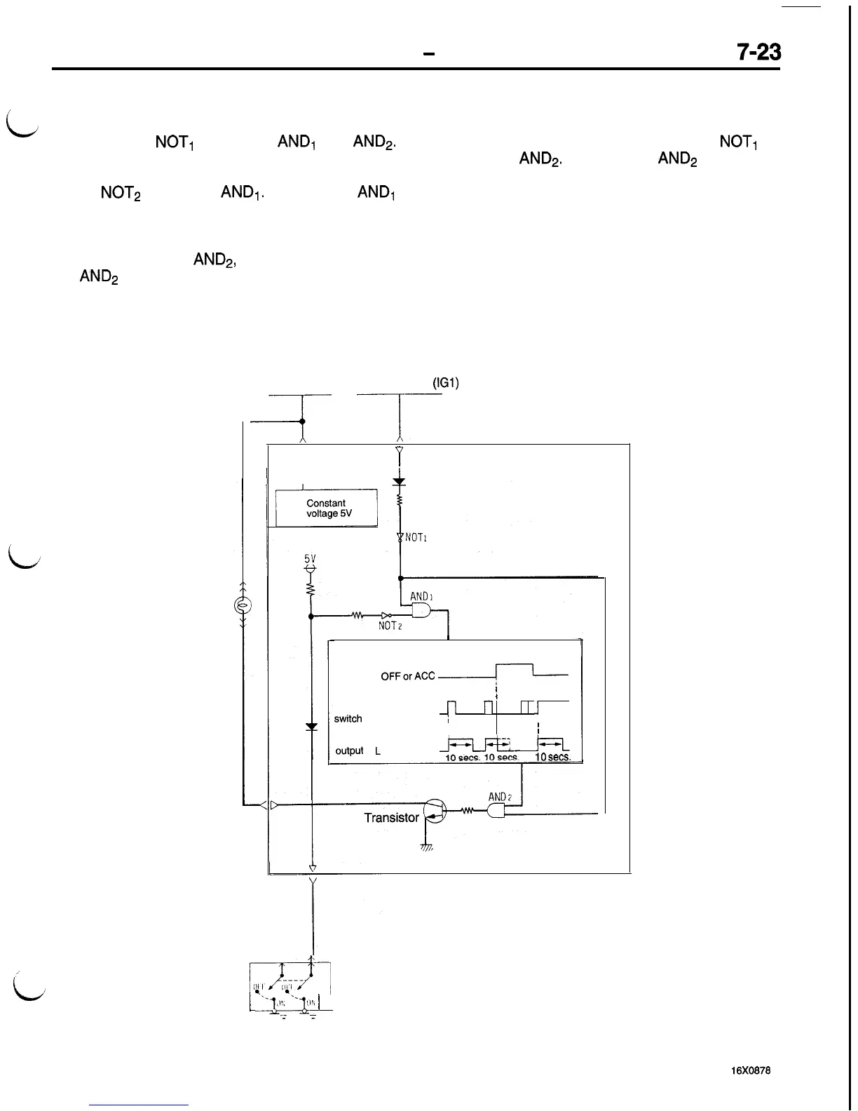
IGNITION SWITCH ILLUMINATION LIGHT TIMER FUNCTION
1.
When the ignition switch is in the OFF or ACC
position, the H signal of the ignition switch in-
verted by
NOT,
is input to
AND,
and
AND2.
2.
When the driver’s door is opened (door switch
ON), the H signal of the door switch inverted
by
NOT2
is input to
AND,.
As a result,
AND1
outputs H signal to cause the timer circuit to
operate.
3.
Accordingly, when the H signal output from the
timer is input to
AND2,
the output signal from
AND2
changes to H signal which causes the
transistor to be ON for 10 seconds to light the
ignition switch illumination light.
Ignition switch
illumination light
4. When the ignition switch is placed in the ON
position during operation of the timer, the L sig-
nal of the ignition switch inverted by
NOT,
is
input to
AND2.
As a result,
AND2
outputs L
signal which causes the transistor to be OFF,
and the ignition switch illumination light goes
out immediately.
NOTE
Even if the driver’s door is opened and closed (door
switch caused to be ON and OFF) while the timer
is in operation, no input signal is accepted.
Fusible link
Ignition switch (IGl)
ii
4
‘(
I
Timer circuit
Ignition ON
switch
OFForACC
-
/
Driver‘s
1
door
(Opened) ON
switch (Closed) OFF
n
l-l
1
,
I
I
Timer
output
H signal (ON)
L
signal
(OFF)
10
sets.
ETACS-ECU
‘E)l,
Driver’s door
1
q..k~~g~.2~
i
switch
T
:
16x0878

 Loading...


