I-34
ENGINE <NON-TURBO>
-
Control System
Test condition
There are a large number of tests waiting to be
performed once the vehicle is stat-ted. It is the diag-
nostic system’s job to see that these tests are not
only performed, but performed under the appropriate
conditions.
An additional job of the diagnostic system is to pre-
vent false
DTC’s
from being stored. The diagnostic
system accomplishes this by not running certain
tests when it recognizes that faults already in the
system or tests currently being run could cause
the next test to fail erroneously. For example:
The test for the catalyst monitor does not run
if the MIL light is on due to an oxygen sensor
fault. The oxygen sensor is a key component
in the catalyst monitor test. If the sensor is not
functioning properly, there is no reason to run
the catalyst monitor
-
it won’t pass. This test
will not be run pending repair of the sensor
concern.
N7lAK30AA
The diagnostic system does not run the test
monitoring catalyst operation if the EGR monitor
‘d
test is being run. The EGR monitor is an “intru-
sive” test and will cause the catalyst monitor
to produce data not representative of normal
operating conditions. This represents a conflict
of test data. The diagnostic system will wait
until the EGR monitor is finished before running
the catalyst monitor.
Finally, the results from the catalyst monitor
are always held until the oxygen sensor test
has been successfully completed. The results
from the test are suspended until the required
prerequisite test has been completed.
By reviewing these guidelines, the diagnostic system
avoids storing
DTC’s
that are the result of failure
of other components in the system. The diagnostic
system allows you to use the diagnostic scan tool
more confidently in diagnosing and repairing a con-
cern.
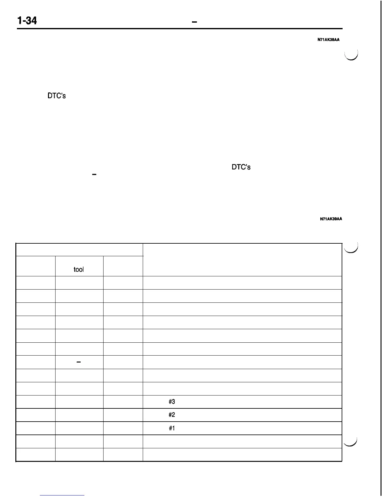
DIAGNOSTIC TROUBLE CODES
N71AK39AA
The diagnostic items are shown in the following table. Note that a fault’s numeric codes are different,
depending on the method of inspection.
Diagnostic trouble code No.
Scan tool
General scan
Diagnostic items
(MUT-II)
tool
MIL
01
PO340
54
No cam signal at PCM
02
PO605
53
Internal controller failure
05
47
Charging system voltage too low
06
46
Charging system voltage too high
10
42
MFI relay (ASD relay) control circuit
11
41
Generator field not switching properly
16
-
33
A/C clutch relay circuit
17
PO403
32
EGR solenoid circuit
18 PO443
31
EVAP solenoid circuit
19 PO203
27
Injector
#3
control circuit
20
PO202
27
Injector
#2
control circuit
21
PO201
27
Injector #l control circuit
25
PO505
25
Idle air control motor circuits
26
PO122
24
Throttle position sensor voltage low
MIL: Check engine/Malfunction indicator lamp
d
d

 Loading...


