6-28
INTERIOR
-
Supplemental Restraint System
(SRS)
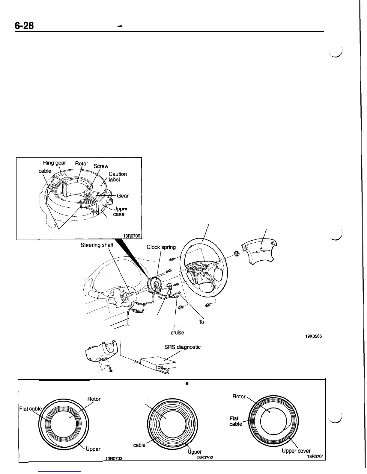
CLOCK SPRING
The clock spring is provided between the steering
wheel (air bag module) and column switch body
(steering column).
The clock spring provides harness connections be-
tween the air bag module and SRS diagnostic unit,
between the horn switch and dashboard wiring har-
ness, and between the remote control switch and
dashboard wiring harness.
The clock spring consists of a neutral position indica-
tion mechanism, flat cable, upper case, lower case,
rotor, etc.
The flat cable is loosely wound like a coil, and is
held in the upper and lower cases with one of its
ends mounted to the rotor and the other end
mounted to the upper case. The upper and lower
cases are mounted to the steering column. The
rotor is coupled with. the steering shaft. Rotation
of the steering wheel (steering shaft) causes the
rotor to rotate. Accordingly, the flat cable is wound
round the rotor or loosened, and operates with the
rotor as the steering wheel is turned.
Caution
Make sure that the clock spring is never disas-
sembled.
Flat
\
Lower case
UV-
Anti-vibration sheet
Cable end support
13R0700
Steering wheel
Air bag module
Body
To air bag
module
I
wiring
/
._
harness
2
horn
To
ciuise
control switch
Q
‘--,&Gnostic
unit
19X0565
When steering whe
!el
is in
neutral position
(straight ahead position)
Flat

 Loading...


