ENGINE <NON-TURBO>
-
Control System
I-53
Bus+ and Bus- Circuits
tmAW1
AA
L
The data transmission system has two wires
con-
from inducing electromagnetic interference
(EMI)
netted in parallel to the PCM and TCM. One circuit
into the bus circuits.
is Bus+, and the other is Bus-. For proper
commu-
nication, the wires must be twisted together at 1.75”
If the twists are not maintained throughout the bus
intervals. Twisting of the wires is intended to prevent
circuits (at connectors and splices), false signals
switched-to-battery or switched-to-ground circuits
can be conveyed to all modules on the bus.
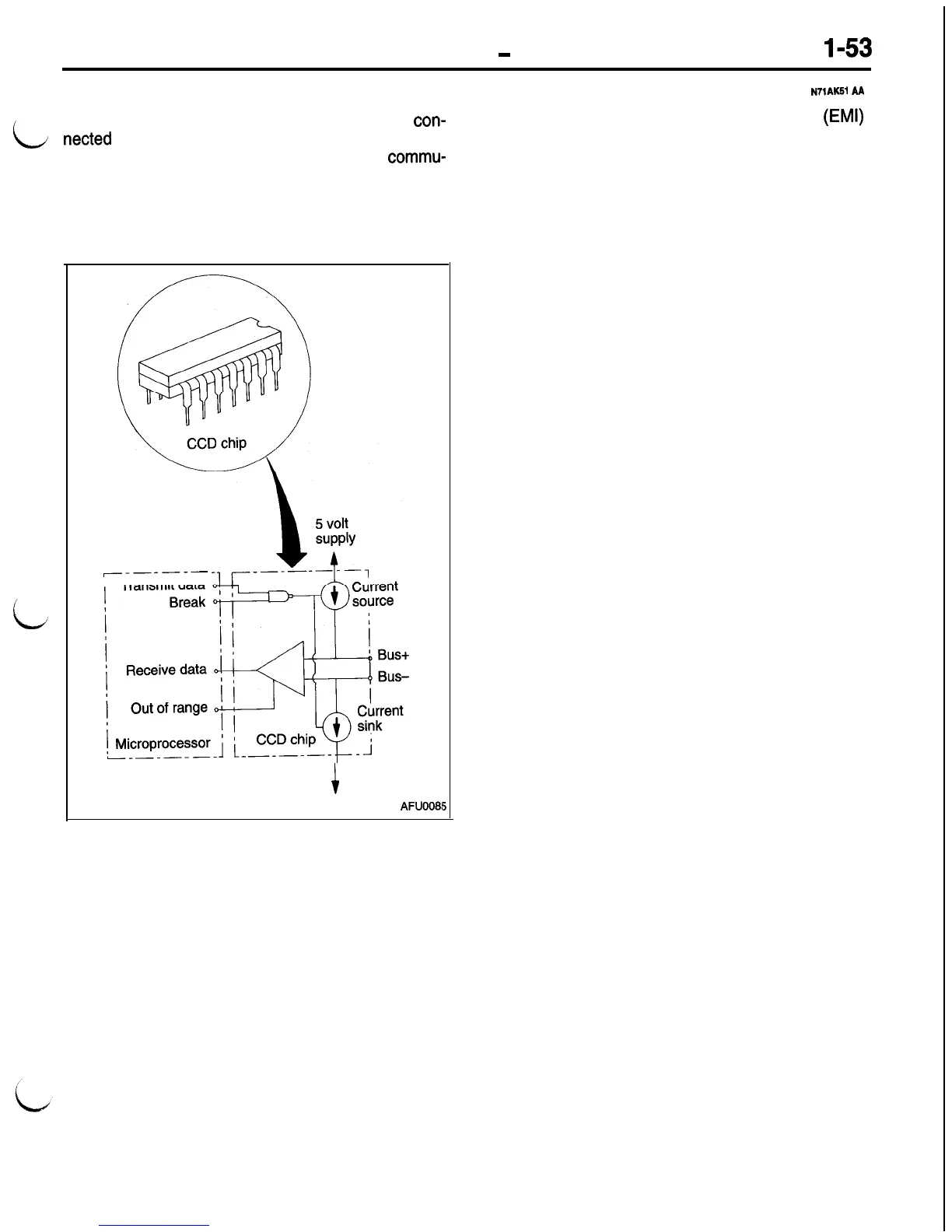
Communication
chip (Communication Control Integrated Circuits)
The bus circuits connect inside all modules to a com-
munication chip. The illustration at left shows a repre-
sentative communication chip block diagram. For
communication to occur, the bus must have Biasing
and Termination (see the following sections.)
i
-------
’
Transmit data
i
AFUOOB!
5

 Loading...


