6-16
INTERIOR
-
Supplemental Restraint System (SRS)
CONSTRUCTION AND OPERATION
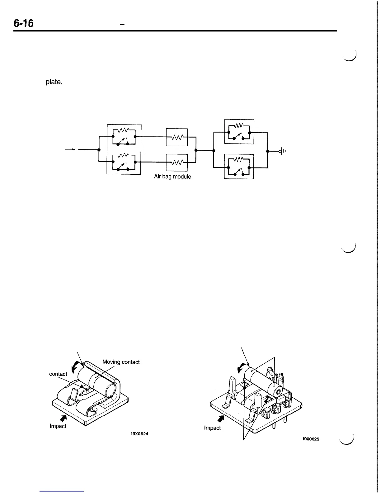
IMPACT SENSORS
There are 2 different types of sensors used; 2 front
built in the SRS diagnosis unit. The right and left
L.&J
impact sensors and safing impact sensor. One front
impact sensor is provided in each of the right and
front impact sensors are connected in parallel.
left shield
pla?e,
and one safing impact sensor is
The front impact sensors are connected in series
with the safing impact sensor.
Safing impact
sensor (Incorporated
in SRS diagnostic unit)
Air bag
module
<Driver’s side>
Front impact
sensor (L.H.)
From
power supply
-----)
<Passenger’s side>
Front impact
sensor (R.H.)
19x0593
If a front-end collision causes either of the front
impact sensors and the safing impact sensor to
be simultaneously “ON”, the air bag will deploy.
They are constructed as shown below and contain
a G sensor each.
The front and safing impact sensors are essentially
identical in construction.
The G sensor consists of a moving contact which
is a roll spring wound around a roller, a fixed contact
positioned in its moving direction, consisting of a
base, a metallic case, etc. If an impact greater than
preset is applied in the direction of the arrow shown
in the illustration, the inertial force causes the roller
Front impact sensor
Safing impact sensor
Roller
Fixed
19X0824
to rotate and move, so that contacts are brought
into the ON stage. To maintain a high measure
of G sensor reliability, the contacts have been gold
plated and the metallic case charged with an inactive
gas.
d
Each impact sensor contains a resistor connected
in parallel with the contacts for detection of a fault
in the wiring. The SRS diagnosis unit always sup-
plies a very small amount of current to the sensor
circuit to monitor a change in the circuit resistance.
Caution
Make sure that the impact sensors are never
disassembled.
Roller
\
Moving contact
Fixed contact
19X0825

 Loading...


