2-90
POWER TRAIN
-
Automatic Transaxle
2s
2ND
I
1ST
1s
q
=
In-gear logic
n
=
Shift logic
1 S,
2s
=
Shift schedule output
1 ST, 2ND
=
Speed ratio shift
complete signal
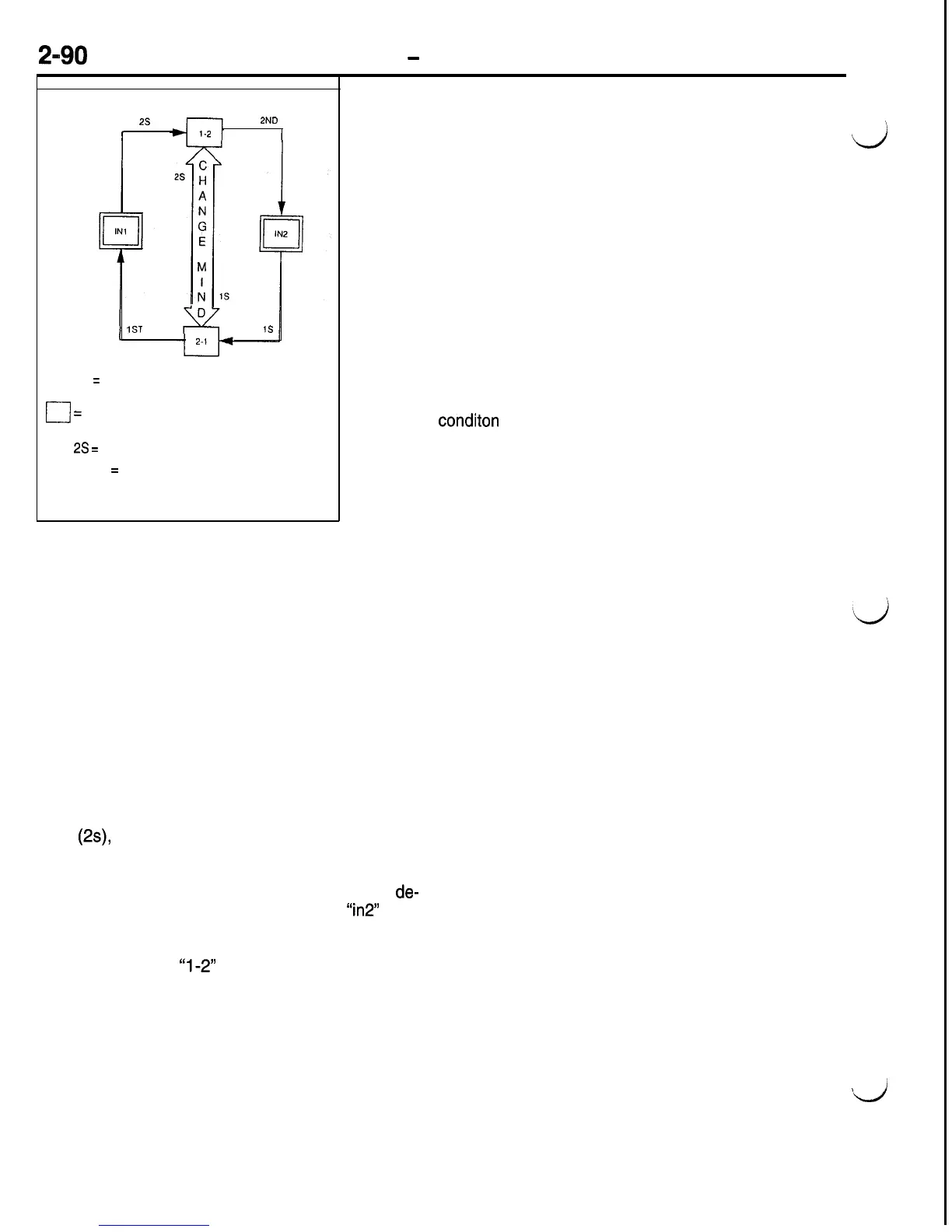
Shift Logic Selection
The purpose of the Shift Logic Selection program is to activate
the appropriate “shift logic” so that the “in-gear logic” condition
d
matches the gear called for by the shift schedule (driver selected
gear, throttle position).
Imagine that the TCM must always be in one of the logic boxes
at any given time. The double line boxes represent the “in-gear
logic” the TCM uses to maintain a certain gear range. The
single line boxes represent the “shift logic” required by the
TCM to execute a desired gear change from one gear to another.
The paths (lines with arrows) between the blocks are labeled
with one or more of the shift schedule output signals (Is, 2s).
These desired gear signals (shift schedule output signals) be-
come the primary input which will cause the correct path to
be taken, from one in-gear box (such as inl) to a shift logic
box (such as l-2).
The output is a change to “shift logic” in order to obtain an
in-gear
conditon
that matches the output of the shift schedule
routine. The TCM knows whether the desired shift has been
completed when a correct speed ratio check of the input and
output speed sensors is present. The speed ratio check is
used to verify that the desired gear has been achieved. For
example, when the correct speed ratio signal for second gear
has been verilied by the TCM by checking the speed ratio
between the input and output speed sensors, it will switch
to the appropriate in-gear logic (in2).
Changes to “In Gear” or “Shift” Logic
If the transaxle is in first gear logic (inl) and the
shift schedule output changes to call for second
gear
(2s),
then “1-2” logic will be activated. This
generally remains in effect until the completion of
the shift is determined by the speed ratio check.
When the speed ratio check confirms that the
de-
gired gear (second) has been obtained,
‘in2”
logic
is activated. There are other possible exits or
changes that may be made to the normal shift sched-
ule logic from the
“1-2”
shift logic example, such
as a change-mind condition.
A “change-mind” shift condition may occur when
a shift that has begun directly from within another
Shift Logic Chart
Another exit or change to the normal shift schedule
logic is the fail shift timer may expire. The TCM
will only allow a certain amount of time to elapse
for the shift logic to complete a shift. If a speed
shift, instead of from an in-gear condition. A “change
mind” condition occurs if a change in the throttle
position signal causes the normal shift schedule
routine to select a different desired gear signal, such
as is, during a 1-2 shift change. These shifts are
accommodated by direct paths between upshift and
downshift logic within the logic selection routine.
“Change mind” shifts are needed to provide the
proper response to changes in driver demand.
Changes in the manual lever (selector lever) position
may also cause a “change-mind” shift depending
on when the lever position changes. A more detailed
shift logic chart is illustrated.
ratio check does not confirm the completion of an
attempted shift within this time limit, the shift logic
’
d
is aborted, and the desired in gear logic is activated.