INTERIOR
-
Supplemental Restraint System (SRS)
6-27
Short bar
Secondary
lock lever
iarness
side connector
13R0667
Pressed down
(Press-fitted terminal
Short bar
13R0688
To body wiring
Press-fitted tab terminals
harness (2-pin)
I\
19X0600
Short terminal (open)
connector t
13R069C
Short terminal
connector
termin
L
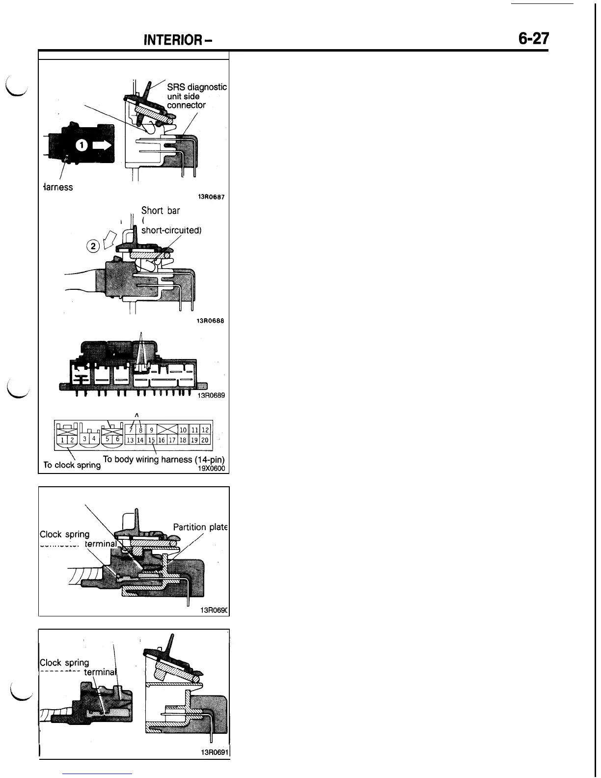
FIT VERIFICATION MECHANISM
The mechanism is used to electrically check the engagement
of the connector between the SRS diagnostic unit and the
body wiring harness. The operating principle is described below.
(1) Securely connect the SRS diagnostic unit and harness
side connectors and press the secondary lock lever down
to lock the connectors.
(2) At this time, the short bar provided on the rear surface
of the secondary lock lever produces a short circuit across
terminals No. 7 and 8 of the SRS diagnostic unit. The
SRS diagnostic unit supplies monitoring current to the circuit
to electrically verify that the connectors have been locked.
CONNECTOR SHORTING MECHANISM
The mechanism is designed for prevention of accidental explo-
sion of the inflator when the clock spring connector (for the
squib circuit) is removed from the SRS diagnostic unit. The
operating principle is described below.
When Connectors are Fitted
When the SRS diagnostic unit and clock spring connector are
coupled, the circuit between the short terminals and clock spring
connector terminals are kept in the OFF state by the partition
plate provided in the connector of the SRS diagnostic unit.
When Connectors are Disconnected
When the clock spring connectors are disconnected from the
SRS diagnostic unit, the partition plate between the short termi-
nals and clock spring connector terminals is removed. As a
result, a short circuit is formed between the two poles of the
clock spring connector terminals to prevent generation of a
potential difference (current) between the squib terminals.
I
13R0691I

 Loading...


