ENGINE
<NON-TURBO>
-
Mount
1-61
MOUNT
<I
id
,
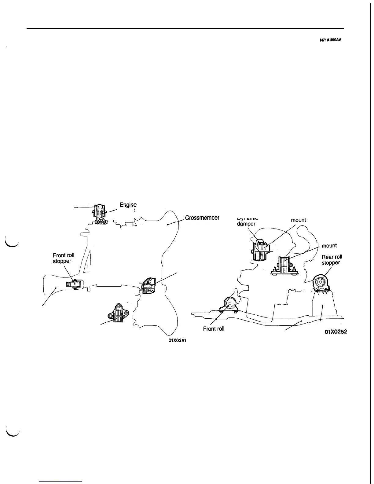
The engine mounts use a principal axis inertia sup-
port system.
This support method on the principal axis inertia
is a structure that supports the top of the engine
FEATURES
l
The mount elements are arranged near the roll
axes of the engine and transaxle so that the
rolling moment can be limited and vibrations
can be reduced during idling.
l
The front and rear roll stopper brackets have
been relocated to the transaxle housing. As
a result, the bracket has been made shorter
and more rigid, which contributes to less vibra-
tion and noise.
l Each insulator with internal hollows has out-
standing vibration absorbing characteristics.
N?‘1AUOOAA
and top of the transaxle to effectively control engine
vibration.
l
Brackets cast from aluminum are used for the
engine mounts and transaxle mounts so as to
reduce booming noise.
l
Conventional arrangement of the engine and
transaxle has been reversed to mount the en-
gine on R.H. side of the vehicle and the transaxle
on the L.H. side, resulting in reversal of the
positions of the respective mounts.
L
Dynamic
damper
LI
,yu
1.z
H
mount
b
wossmemuer
Dynamic
Engine
damp&&
Transaxle
Front
Rear roll
stopper
Centermember
Transaxle
I
mount
01X0251
stopper
Centermember
u
Crossmember
01X0252
i
:

 Loading...


