id
i;
L
EQUIPMENT
-
ETACS
7-25
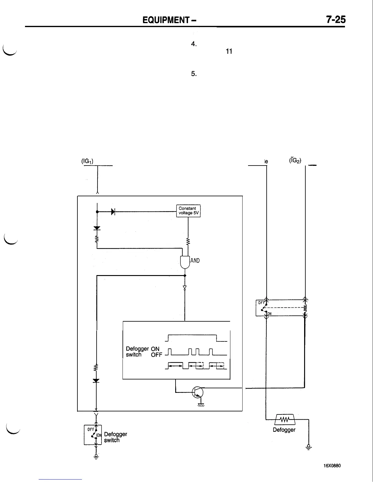
DEFOGGER TIMER FUNCTION
1. When the ignition switch is turned to the ON
position, the H signal of the ignition switch and
the H signal of the constant voltage are input
to AND. As a result, AND outputs H signal.
2.
When the defogger switch is placed in the ON
position, the H signal inverted by NOT is input
to timer circuit to activate the timer circuit.
3. Since the defogger switch (auto reset switch)
placed in the ON position is automatically reset
to the OFF state, the L signal which is opposite
to the signal in Item (2) is input to the timer
circuit after the switch has been caused to be
ON, but the timer keeps on operating.
The timer output causes the transistor to be
ON for
II
minutes. The defogger relay is also
placed in the ON position to operate the defog-
ger.
When the ignition switch is placed in the OFF
position or when the defogger switch is placed
in the ON position again during operation of
the timer, the H signal is input to the timer circuit
again. As a result, the timer circuit stops operat-
ing, and the transistor is forced to the OFF state.
The defogger relay is also placed in the OFF
oosition and the defogger stops operating.
Ignition switch
WI)
-I-
NOT
Timer circuit
Ignition ON
switch
OFF
m
s”w”&fger
g:F
a
Timer ON
m
output
OFF
-
-1
7
11 mins 11 mins 11 mins
Transistor
OFF
3
.
ON
~;f#c.w
ETACS-ECU
Fusibl
Ignition switch
le
link
(iG2)
--
-
1
Defogger
relay

 Loading...


