7-33
Chapter 7 ASSEMBLY OF BASIC ENGINE
5.13 Valve Clearance - Check and Adjust
Adjust the valve clearance when the engine is cold.
Note:(a) The inlet valves are on the left side and exhaust
valves are on the right when the cylinder head is
viewed from camshaft side.
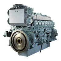
(b) The valve clearance standard values are shown on
the caution plate on the No. 1 cylinder rocker cover.
(1) Adjust the valve clearance in the firing order at TDC of
compression stroke by turning crankshaft in the normal
direction.
(2) On each cylinder, the piston is at the top dead center on
compression stroke, when corresponding cylinder num-
ber stamped on damper is aligned with pointer, and
inlet valves and exhaust valves are not pushed with
push rod.
(3) Insert a thickness gauge between rocker arm and bridge
cap to measure the clearance. Tighten or loosen the
screw to adjust the clearance where the movement of
thickness gauge becomes slightly restricted.
(4) After the adjustment tighten the lock nut firmly to the
specified torque. Then, check the clearance again.
Valve Clearance Label - Location
No. 1 Cylinder Compression Top Dead Center - Check
Valve Clearance - Adjust
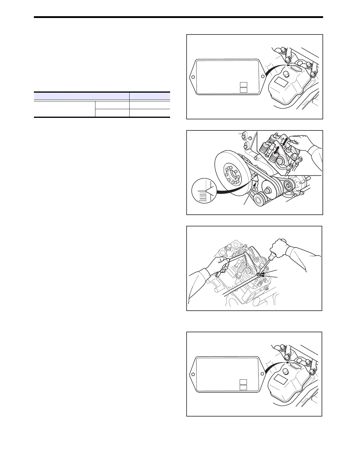
5.14 Fuel Injection Timing - Check and Adjust
5.14.1 Specified Value of Fuel Injection Timing - Check
The fuel injection timing varies depending on the engine
output, speed and specifications. Be sure to check the plate
on the No. 1 rocker cover for the fuel injection timing.
Specified Value of Fuel Injection Timing - Check
Item Standard value
Valve clearance
Inlet 0.4 mm [0.016 in.]
Exhaust 0.5 mm [0.019 in.]
8#.8'%.'#4#0%'%1.&
+0.'6
(+4+0) 14&'4
(7'.+0,'%6+106+/+0)
':*#756
OO
OO
$6&%
q
%1041&4#0-
・
Pointer
Cylinder firing order:
1-12-5-8-3-10-6-7-2-11-4-9
Screw
Lock nut
64 ± 6.4 N·m
{6.5 ± 0.65 kgf·m}
[47 ± 4.7 lbf·ft]
8#.8'%.'#4#0%'%1.&
+0.'6
(+4+0) 14&'4
(7'.+0,'%6+106+/+0)
':*#756
OO
OO
$6&%
q
%1041&4#0-

 Loading...