7-8
Chapter 7 ASSEMBLY OF BASIC ENGINE
2. Cylinder Liner, Piston and Connecting Rod - Assemble
2.1 Cylinder Liner Protrusion - Measure
(1) Place the dial gauge probe on the top surface of cylin-
der liner flange, and adjust the dial gauge to zero.
(2) Slide the probe to measure the protrusion of the cylin-
der liner at four places.
(3) If the value exceeds the limit, or if the ridge is cracked,
replace the cylinder liner with a new one.
Cylinder Liner Protrusion - Measure
2.2 Cylinder Liner Flange Protrusion - Calculate (When Cylinder Liner Not Installed)
(1) Inspect the cylinder liner contact surface on the crank-
case.If uneven contact is shown, reface the counterbore
with the crankcase grinder to correct the depth differ-
ence at four places in circumference to be less than 0.05
mm [0.0020 in.]
For repair procedure, refer to "Counterbore in Crank-
case - Repair" of "INSPECTION AND REPAIR OF
BASIC ENGINE."
(2) Make sure that the top and bottom faces of cylinder
liner flange, the top surface of crankcase and the fitting
surfaces of cylinder liner are clean before measure-
ment.
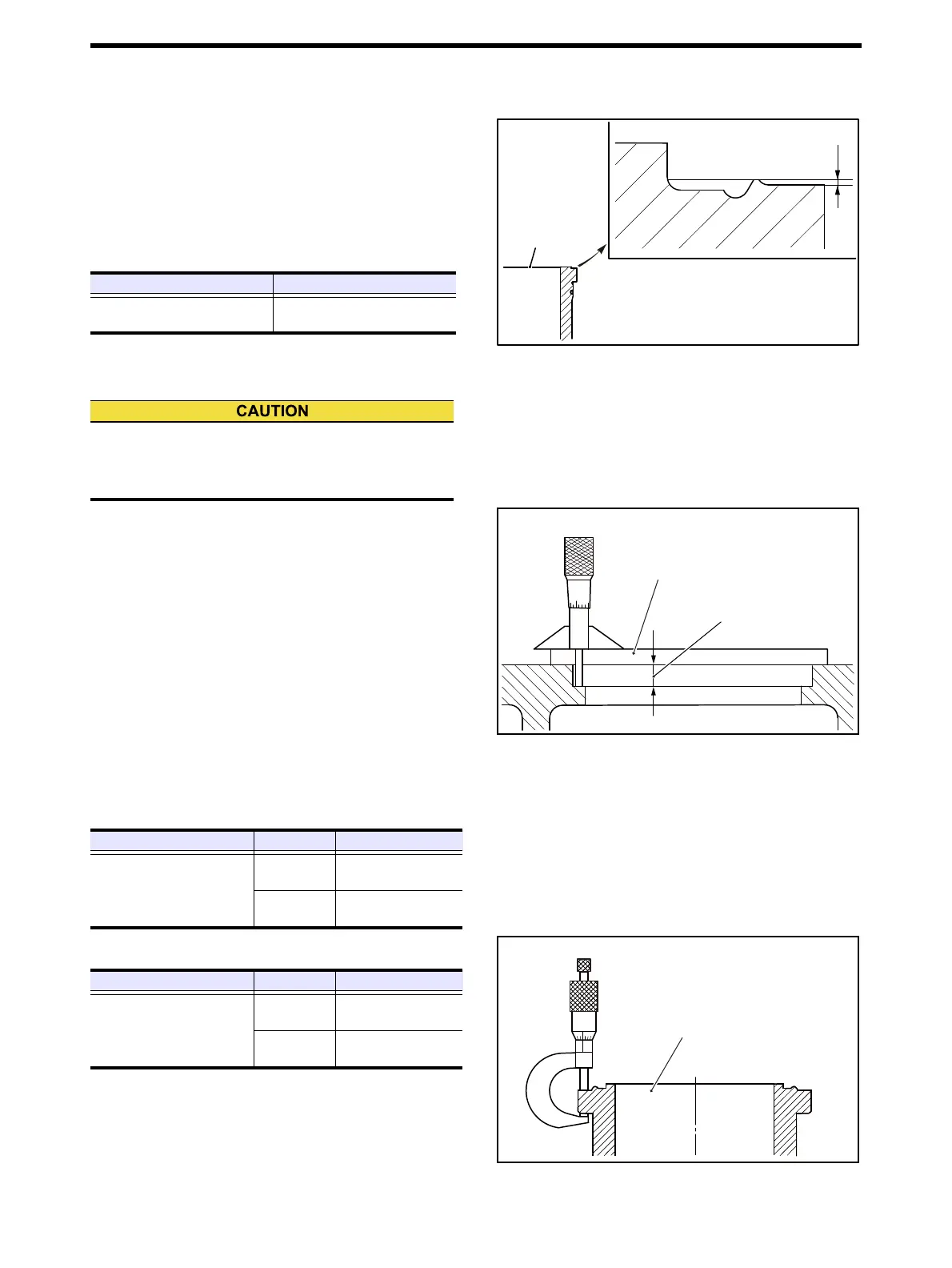
(3) Measure the depth of counterbore in crankcase.
Depth of counterbore in crankcase - Measure
(4) Measure the thickness of cylinder liner flange.
Thickness of cylinder liner flange
Item Standard value
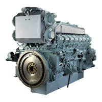
Cylinder liner protrusion
0.16 to 0.24 mm
[0.0063 to 0.0094 in.]
Height of protrusion
Cylinder liner
top face
If the amount of protrusion is not enough, the contact
pressure of cylinder head gasket is low, and it can
result in gas and water leakage.
Item Part No. Standard value
Depth of counterbore in
crankcase
32608-00200
(S12A2-1)
12.00 to 12.05 mm
[0.4724 to 0.4744 in.]
32608-00300
(S12A2-2)
15.00 to 15.05 mm
[0.5906 to 0.5925 in.]
Projection plate
P/N:37598-09201
Counterbore depth
Item Part No. Standard value
Thickness of cylinder liner
flange
32507-62400
(S12A2-1)
12.15 to 12.19 mm
[0.4783 to 0.4799 in.]
32607-03400
(S12A2-2)
15.15 to 15.19 mm
[0.5965 to 0.5980 in.]
Cylinder liner

 Loading...