8-37
Chapter 8 FUEL SYSTEM
3.2 Fuel Control Link - Install
3.2.1 Control shaft - Install
Control shaft - Install
(1) Insert the pipe with O-ring to the timing gear case.
(2) Insert the control shaft to the pipe.
(3) Press-in bearings to control shaft both ends.
(4) Install the snap ring to left control shaft. (Mechanical governor spec, PSG governor spec)
(5) Install the bearing cover.
(6) With a plastic head mallet, tap the both ends of control shaft alternately for snug fitting.
(7) Rotate the control shaft by hand, and verify the smooth rotation.
3.2.2 Control Link Lever - Install
(1) Install the link levers of both banks (stamped mark : L and R) together with ball bearing, snap ring and bearing cover to the
stay.
(2) Tentatively install the control lever having a serrated hole to the right end of control shaft.
(3) Tentatively install the link lever, which is connected to the governor, together with the ball bearing, snap ring, and stop
lever to the left end of control shaft.
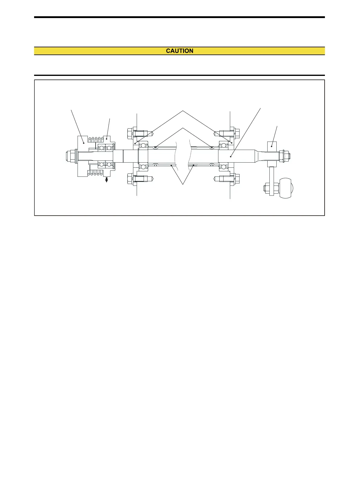
If the bearings at both ends of control shaft are not properly installed, or if the bearings do not rotate smoothly, it
could result in a hunting or other malfunctions.
Stop lever
Link lever
Bearing cover
To governor
Pipe
O-ring
Control shaft
Control lever
Left side of engine Right side of engine

 Loading...