8-42
Chapter 8 FUEL SYSTEM
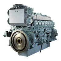
Right-bank linkage - Overall view
(1) Set the length of the link A between the fuel injection
pump rack and the control link lever (for both right and
left banks) to 126.5±0.3 mm [4.98±0.012 in.], and
install the link A to the right and left banks respectively.
(2) Install the right-bank variable length control link B-1
(140.5±0.3 mm [5.53±0.012 in.]) between the control
link lever and control lever.
(3) Set the left-bank variable-length control link B-2 to
147 mm [5.79 in.], and fit the link to the stop lever hav-
ing a serration hole.
Check that the fuel injection pump racks of both banks
are at the no-injection position, then install the stop
lever together with the spacer and cancel spring to the
serration on the control shaft.
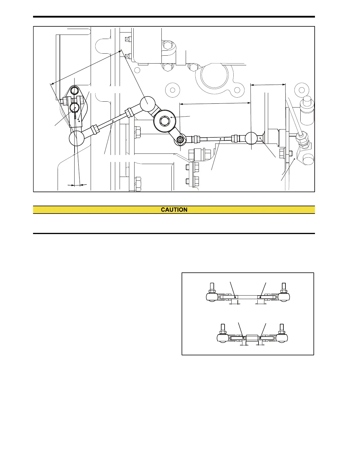
Note: Adjust the engagement lengths even on right and left-
handed threads.
Right and left-bank control links
(4) Fine adjust the left-bank variable-length control link C
so that both right and left-bank fuel injection pump
racks move the same distance.
Adjustable length control rink A
Fuel injection pump
Control lever
140.5± 0.3 mm
[5.532± 0.012 in.]
Adjustable length control link B-1
4°
Control rack
126.5 ± 0.3 mm
[4.980 ± 0.012 in.]
Control shaft
Woodward ProAct actuator spec
Toho Seisakusho SG4017 actuator PTA2 spec
Distance from the end of
fuel injection pump to
the hole center at rack end
Rack "0": 67.5 mm [2.60 in.]
Play: approx. 2 mm [0.12 in.]
Control link lever
140.5± 0.3 mm
[5.532± 0.012 in.]
If the play of fuel injection pump rack is in excess, fuel can not be stopped even when the governor brings the link to
engine stop position, and engine over-running may results.
Left-hand thread
Right-hand thread
Left-hand thread
Right-hand thread
Make the length of engagements even.
Make the length of engagements even.

 Loading...