Chapter 8 Disassembly/Reassembly Procedures
8.1 Introduction
This section details the procedures necessary to remove and replace the printed circuit boards in the
ASTRO Digital Spectra and Digital Spectra Plus radios. After troubleshooting and determining which
board needs to be replaced, disconnect the test equipment, the antenna cable, and unhook the dc
power.
Locate the exploded view drawing of the radio in
Chapter 11: Exploded Views and Parts Lists. Keep
it handy for reference when disassembling and reassembling the radio.
When installing a new circuit board, all mounting screws should be started before any are torqued.
This helps assure proper board alignment with the chassis.
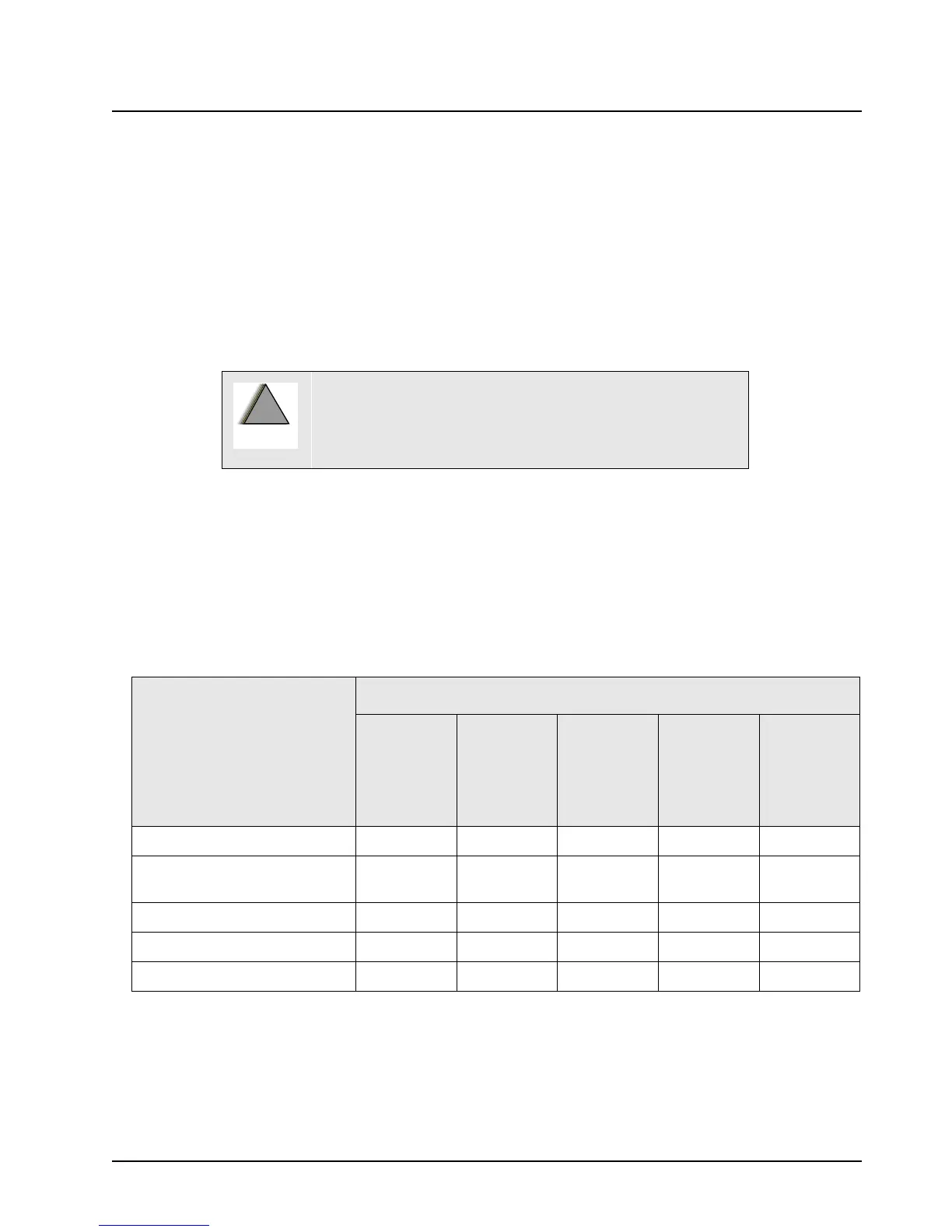
After installing a new board, refer to
Table 8-1 and perform the alignment procedures indicated for
the replaced board.
8.2 Replacement Procedures
NOTE: After performing alignment procedures, always exit the SERVICE menu entirely (to the MAIN
MENU) to save all changes properly. Failure to do so can result in a alignment (or other)
failure.
Disconnect all dc power to the radio before removing any
boards from the radio. Failure to remove power can result
in unit damage caused by transients or accidental shorts,
as well as a shock hazard.
Table 8-1. Required Alignments After Board Replacement
Board Replaced Alignment Required
Reference
Oscillator
Transmit
Deviation
Balance
(compen-
sation)
Transmit
Deviation
Limit
Transmit
Power
Transmit
Current
Limit
Command Board X
VCO (Voltage Controlled
Oscillator)
XX
RF (Radio Frequency) Board X X X
PA (Power Amplifier) Board X X
VOCON Board XXXXX
!
 Loading...


