February 3, 2003 6881076C20-E
8-2 Disassembly/Reassembly Procedures: Replacement Procedures
8.2.1 Required Tools and Supplies
8.2.2 Control Head Boards
8.2.2.1 Model W3
NOTE: Numbers shown in brackets in the following procedure refer to item numbers in Figure 11.1:
“Model W3 Hand-Held Control Head Exploded View,” on page 11-2
, and in Table 11.1, “Model
W3 Hand-Held Control Head Exploded View,” on page 11-2
.
1. Remove the strain-relief boot (part of cable assembly [15]) from the housing assembly [7] by
applying downward pressure on the boot and pulling it away from the control head until they
are completely separated.
2. Carefully remove the rubber seal (part of cable assembly [15]) from the housing assembly [7]
opening.
NOTE:Take care to avoid damaging this seal.
3. Using a small screwdriver, remove the seal support wedge [14] from the control head.
4. Using a small screwdriver to depress the telco lever, remove the telco connector (part of
cable assembly [15]) from the control head, and pull the cable assembly away from the
housing (like a telephone jack).
5. Remove the rear cover assembly [2] from the control head.
6. Locate the recesses in the lower portion of the housing on both sides of the rear cover’s snap
features and, prying the snaps until the two parts separate, remove the rear cover from the
unit.
7. Remove the two snap retainers [4] from between the circuit board [5] and the housing
assembly [7].
8. Disconnect the microphone assembly [8] connector from the circuit board [5].
9. Carefully remove the microphone cable assembly from the keypad [6].
10. Carefully pry the housing’s snap features from the circuit board [5].
NOTE:Be careful to avoid damaging circuit board components.
There are seven snaps locking the circuit board to the housing. As the snap features are deflected,
push the circuit board upward, using the keypad, to release the circuit board from the snap features.
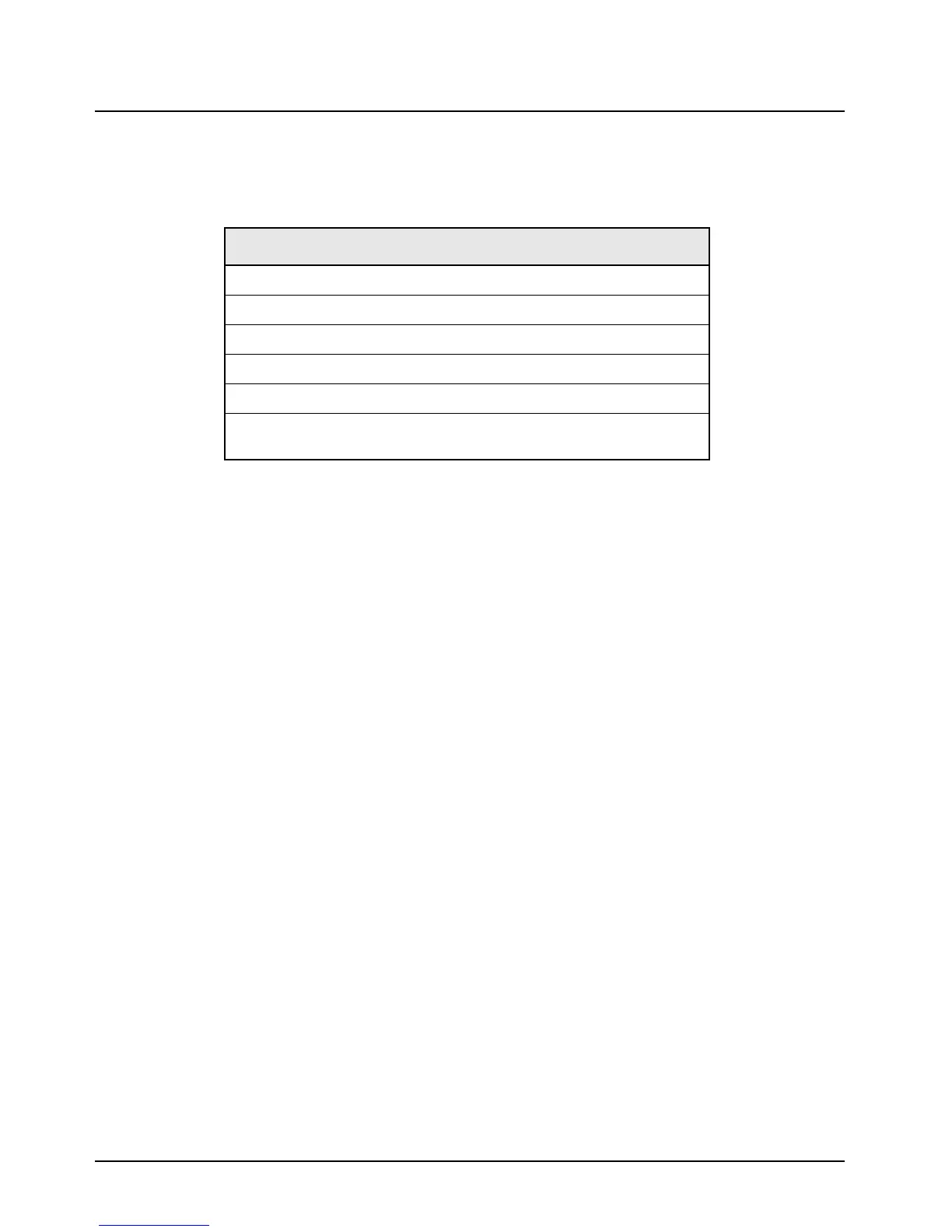
Table 8-2. Required Tools and Supplies
Tools and Supplies
Small, flat-blade screwdriver
2.5 mm hex-key driver
Torx® T8, T10, and T15 drivers
3.0 mm Allen wrench
Thermal compound (Motorola part number 11-83166A01, or equivalent)
Electromagnetic Interference (EMI) metallic shielding tape (Motorola part
number 11-85984D01, or equivalent)
 Loading...


