6881076C20-E February 3, 2003
Disassembly/Reassembly Procedures: Replacement Procedures 8-9
6. Use a Torx T15 driver to remove the larger screws. (Five screws are used on 15-watt, six on
the 20- and 35-watt.)
7. Carefully lift the PC board from the heatsink.
NOTE:Before unsoldering the RF cables, note which cable is attached to each connector
on the board. This will facilitate assembly since the cables differ in length.
8. Unsolder the antenna coax cable attached to the bottom of the board.
9. Unsolder and remove the power module shield.
10. Unsolder the RF cables from the board.
8.2.5.3.3 PC Board Installation
1. Solder the RF cables to the board connectors.
2. Clean any old thermal compound from the mounting surfaces of the power transistor, power
module, and (on 20- and 35-watt models) the final device.
If the power transistor insulator was not disturbed, it is not necessary to clean beneath it.
3. Apply a new, uniform coat of thermal compound (e.g., Motorola part no. 11-83166A01), which
is thick enough to fill all small air voids, to the mounting surfaces.
NOTE:Do not use a thick coating of compound and do not allow any small bits of dirt or
debris to get in the compound; such would degrade the thermal efficiency of the
heatsink.
4. Solder the three leads of the Q9500 pass device.
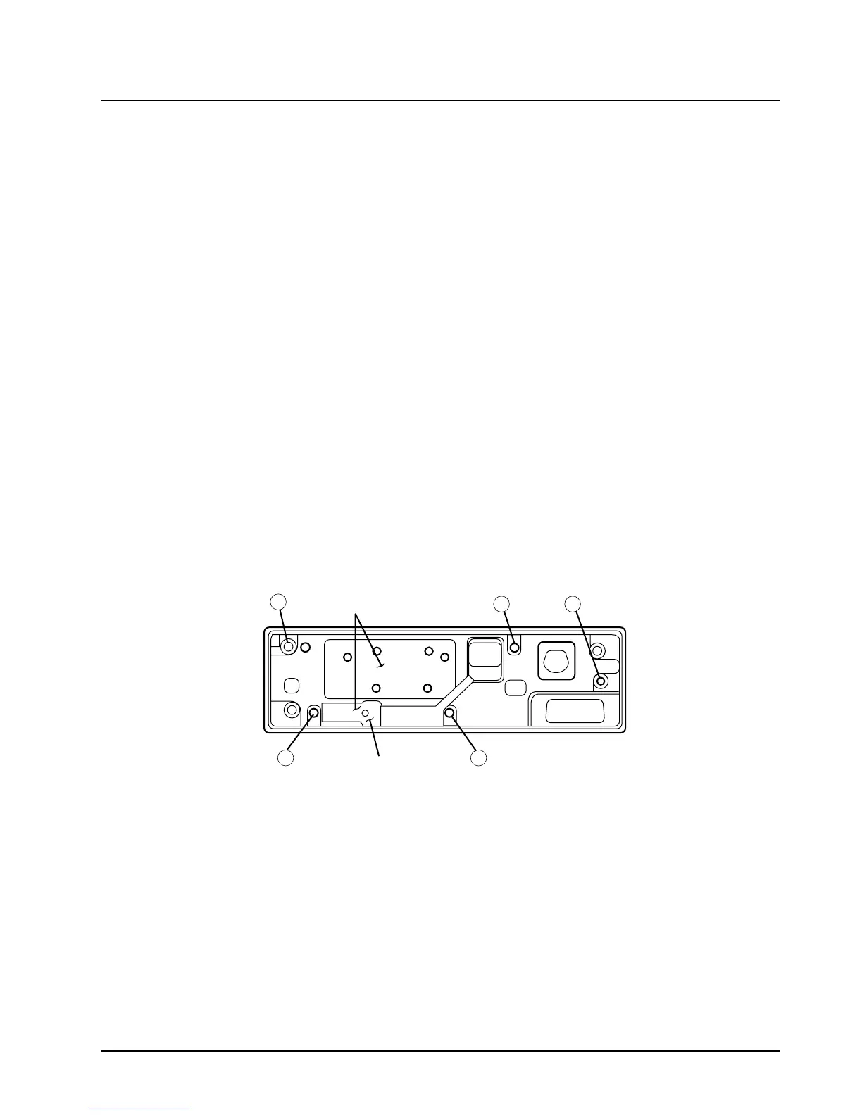
5. Install the PC board, and then attach and tighten the screws (torque 8-10 in.-lbs.) in the
sequence shown in
Figure 8-3.
Figure 8-3. PA Board Screw Fastening Sequence (800 MHz 15-Watt PA)
6. 20- and 35-watt radios only: Install the final device with two screws (torque 8-10 in.-lbs.). The
properly oriented final device is shown in
Figure 8-4.
12
34
5
APPLY TERMINAL
COMPOUND HERE
PASS DEVICE
INSULATOR HERE
 Loading...


