Home
Motorola
Radio
ASTRO SPECTRA
Motorola ASTRO SPECTRA Service Manual
4
of 1
of 1 rating
176 pages
Give review
Manual
Specs
To Next Page
To Next Page
To Previous Page
To Previous Page
Loading...
10-6
Functional Block Diagrams a
nd Connectors
: Extende
r Cable (P501)
February 3, 200
3
6881076C20-E
10.6
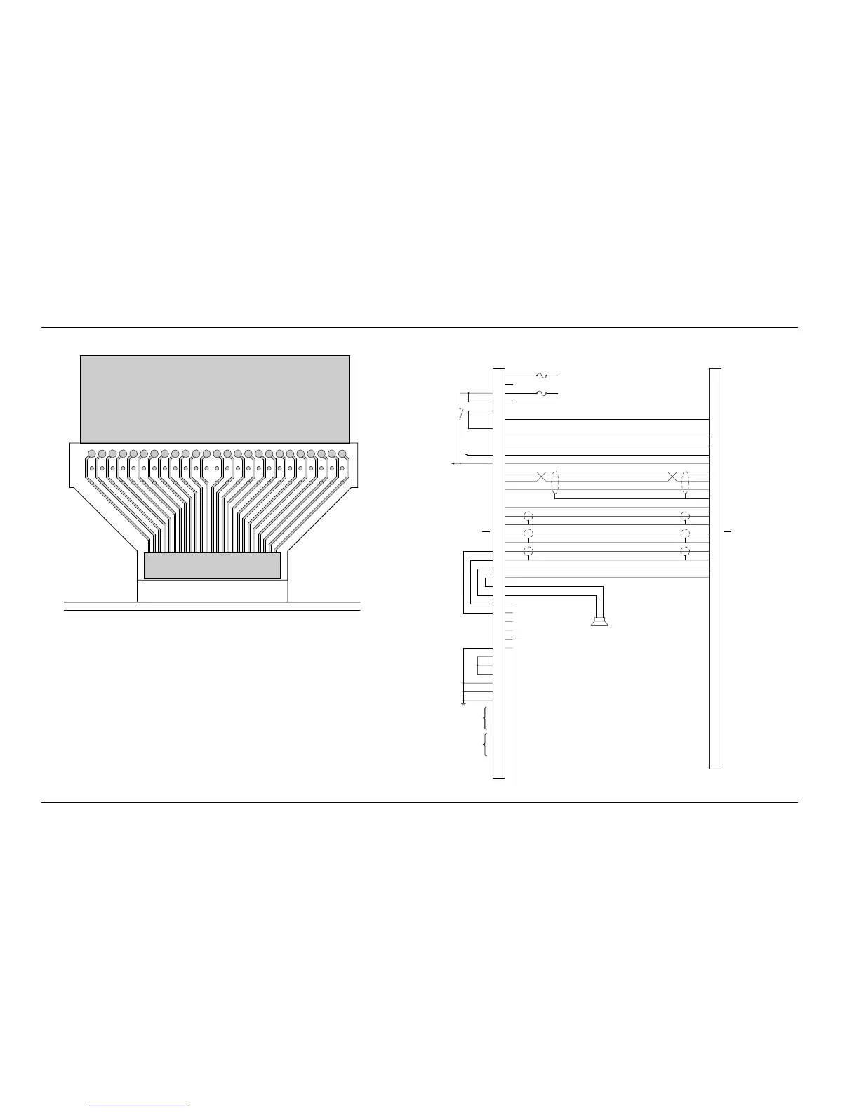
Extender Cable (P501)
Figure 10-12. P501
Extender Cable
10.7
Control Head C
abling Diagram
Figure 10-13. Cont
rol Head Cabling Di
agram
15
17
1
9
1
3
1
1
97531
21
23
25
27
29
31
33
35
37
39
41
43
45
47
49
16
18
20
14
12
10
8
642
22
24
26
28
30
32
34
36
38
40
42
44
46
48
50
P501
EXTENDER
CABLE
(3080370E06)
(FACING TOWARD
CONTROL HEAD)
J501
COMMAND BOARD
P1001
SPARE 2
EMERGENCY
SPARE 1
DIG GND
SWB+
BUS +
BUS -
BUSY
BUS SHIELD
RESET
DET AUDIO
ANA GND
PTT
MIC HI
MIC LO
SPKR HI
SPKR LO
A+
RSSI
RX AUDIO
RED
VIO
BRN
BLU
YEL
WHT
BLK
BLK/RED
BARE
BLK/ORG
BLK/BRN
SHIELD
BLK/GRN
SHIELD
BLK/YEL
SHIELD
ORG
GRN
CONTROL HEAD
ORG
GRN
NC
NC
MIC LO
MIC HI
SWB+
HUB
PTT
PTT/HUB REF
SWB+
SWB+
SWB+
DIG GND
DIG GND
DIG GND
(DATA IN)
(STROBE)
(CLOCK)
(DATA OUT)
BUS +
BUS -
BUSY
RESET
DET AUDIO
ANA GND
PTT
IGN+
IGN-
BATT+
BATT+
BATT-
SPARE 2
BATT-
EMERGENCY
SPARE 1
BLK/GRN
BLK/ORG
DIG GRD
SWB+
P5
RADIO
15
32
47
30
31
29
14
27
28
49
48
17
50
33
26
45
16
46
12
13
44
11
10
43
7
8
41
40
24
23
18
19
3
20
21
36
4
3
37
2
1
34
38
5
SPEAKER
17
13
16
18
22
5
14
23
21
19
9
0
1
12
11
25
24
20
15
7
1
2
3
1
2
3
VIP IN
VIP OUT
147
149
Table of Contents
Default Chapter
3
Motorola, Inc
3
Foreword
4
Manual Revisions
4
Computer Software Copyrights
4
Document Copyrights
4
Disclaimer
4
Trademarks
4
Table of Contents
5
Commercial Warranty
15
Limited Warranty
15
Motorola Communication Products
15
General Provisions
15
What this Warranty Covers and for How Long
15
How to Get Warranty Service
16
State Law Rights
16
What this Warranty Does Not Cover
16
Governing Law
17
Patent and Software Provisions
17
Model Numbering, Charts, and Specifications
18
Mobile Radio Model Numbering Scheme
18
ASTRO Digital Spectra Motorcycle 15 Watt (Ranges 1 and 2) Model Chart
19
ASTRO Digital Spectra Motorcycle 15 Watt (Ranges 3 and 3.5) Model Chart
20
ASTRO Digital Spectra VHF 10-25 Watt Model Chart
21
ASTRO Digital Spectra VHF 25-50 and 50-110 Watt Model Chart
22
ASTRO Digital Spectra VHF 10-25 and 50-110 Watt Model Chart (Cont.)
23
ASTRO Digital Spectra UHF 10-25 Watt Model Chart
24
ASTRO Digital Spectra UHF 20-40 Watt Model Chart
25
ASTRO Digital Spectra UHF 20-40 Watt Model Chart (Cont.)
26
ASTRO Digital Spectra UHF 50-110 Watt Model Chart
27
ASTRO Digital Spectra UHF 50-110 Watt Model Chart (Cont.)
28
ASTRO Digital Spectra 800 Mhz Model Chart
29
ASTRO Digital Spectra Plus VHF 25-50 and 50-110 Watt Model Chart
30
ASTRO Digital Spectra Plus VHF 25-50 and 50-110 Watt Model Chart (Cont.)
31
ASTRO Digital Spectra Plus UHF 20-40 Watt Model Chart
32
ASTRO Digital Spectra Plus UHF 20-40 Watt Model Chart (Cont.)
33
ASTRO Digital Spectra Plus UHF 50-110 Watt Model Chart
34
ASTRO Digital Spectra Plus UHF 50-110 Watt Model Chart (Cont.)
35
ASTRO Digital Spectra Plus 800 Mhz Model Chart
36
ASTRO Digital Spectra Plus 800 Mhz Model Chart (Cont.)
37
VHF Radio Specifications
38
UHF Radio Specifications
39
800 Mhz Radio Specifications
40
Chapter 1 Introduction
41
Notations Used in this Manual
41
Radio Descriptions
41
Flashport
42
Control Head Descriptions
42
General
42
Table 1-1. ASTRO Digital Spectra/Spectra Plus Basic Features
42
Figure 1-1. Typical W3 Hand-Held Control Head
43
Model W3 Control Head
43
Model W3 Controls
43
Figure 1-2. Typical W4 Rotary Control Head
44
Figure 1-3. Typical W5 Pushbutton Control Head
44
Figure 1-4. Typical W7 Pushbutton Control Head
44
Models W4, W5, W7, and W9 Controls Head
44
Figure 1-5. Typical W9 Pushbutton Control Head
45
Models W4, W5, W7, and W9 Controls
45
Chapter 2 Basic Maintenance
47
Introduction
47
Preventive Maintenance
47
Reference Oscillator
47
Inspection
47
Cleaning
47
Cleaning External Plastic Surfaces
48
Cleaning Internal Circuit Boards and Components
48
Handling Precautions
48
Chapter 3 Basic Theory of Operation
51
Introduction
51
General Overview
51
Analog Mode of Operation
52
Receive Operation
52
Transmit Operation
52
ASTRO Mode of Operation
52
Control Head Assembly
52
Display (W4, W5, and W7 Models)
52
Display (W9 Model)
53
Vacuum Fluorescent (VF) Display Driver
53
Vacuum Fluorescent (VF) Voltage Source (W9 Model)
53
Controls and Indicators
53
Status Leds
53
Backlight Leds
53
Vehicle Interface Port (VIP)
54
Dash-Mount
54
Remote-Mount
54
Power Supplies
54
Ignition Sense Circuits
54
Power Amplifier
54
Gain Stages
54
Power Control
55
Circuit Protection
55
DC Interconnect
55
Front-End Receiver Assembly
55
Radio Frequency (RF) Board
55
Voltage-Controlled Oscillator (VCO)
56
VHF Radios
56
UHF and 800 Mhz Radios
56
Command Board
56
VOCON (Vocoder/Controller) Board
57
ASTRO Digital Spectra
57
ASTRO Digital Spectra Plus
57
Chapter 4 Test Equipment, Service Aids, and Tools
59
Recommended Test Equipment
59
Table 4-1. Recommended Motorola Test Equipment
59
Service Aids and Recommended Tools
60
Table 4-2. Wattmeter Plug-In Elements
60
Table 4-3. Recommended Non-Motorola Test Equipment
60
Table 4-4. Common Service Aids for Board-Level Troubleshooting
61
Table 4-5. Service Aids for ASTRO Digital Spectra Board-Level Troubleshooting
62
Field Programming Equipment
63
ASTRO Digital Spectra
63
Table 4-6. Service Aids for ASTRO Digital Spectra Plus Board-Level Troubleshooting
63
Table 4-7. Recommended Tools for Board-Level Troubleshooting
63
ASTRO Digital Spectra Remote W3 y Cable
64
ASTRO Digital Spectra W3 Smart RIB Issue
64
Table 4-8. ASTRO Digital Spectra Field Programming Items
64
ASTRO Digital Spectra Plus
65
ASTRO Digital Spectra Plus Model W3
65
Table 4-9. ASTRO Digital Spectra Plus Field Programming Items
65
Chapter 5 Performance Checks
67
Introduction
67
Test Setup
67
ASTRO Digital Spectra
67
ASTRO Digital Spectra Plus
67
Figure 5-1. ASTRO Digital Spectra Performance Checks Test Setup
67
Test Mode
68
Entering Test Mode
68
Figure 5-2. ASTRO Digital Spectra Plus Performance Checks Test Setup
68
Table 5-1. Test-Mode Displays
68
RF Test Mode
69
Table 5-2. Test Frequencies
70
Control Head Test Mode
71
Figure 5-3. Rotary Control Head Key-Closure Displays (W4)
71
Table 5-3. Signaling Types
71
Receiver Performance Checks
72
Figure 5-4. Pushbutton Control Head Key-Closure Displays (W5 and W7)
72
Figure 5-5. Pushbutton Control Head Key-Closure Displays (W9)
72
Table 5-4. Receiver Performance Checks
72
Transmitter Performance Checks
73
Table 5-5. Transmitter Performance Checks
73
Chapter 6 Radio Alignment Procedure
75
Introduction
75
Rss
75
ASTRO Digital Spectra
75
Figure 6-1. ASTRO Digital Spectra Radio Alignment Test Setup
75
Softpot
76
Figure 6-2. RSS Service Menu Layout
76
Figure 6-3. Softpot Concept
76
Reference Oscillator Alignment
77
Transmit Power Alignment
78
Figure 6-4. Reference Oscillator Alignment Screen
78
Table 6-1. Reference Oscillator Alignment
78
Figure 6-5. Transmit Power Alignment Screen
79
Table 6-2. Transmit Power Settings
79
Transmit Current Limit Alignment
80
Figure 6-6. Transmit Current Limit Alignment Screen
80
Transmit Deviation Balance (Compensation) Alignment
81
Transmit Deviation Limit Alignment
82
Figure 6-7. Transmit Deviation Balance (Compensation) Alignment Screen
82
Figure 6-8. Transmit Deviation Limit Alignment Screen
83
Bit Error Rate (BER) Performance Check
84
ASTRO Digital Spectra and Digital Spectra Plus Tuner Software
84
Figure 6-9. ASTRO Digital Spectra Plus Radio Alignment Test Setup
85
Figure 6-10. Tuner Menu Layout
86
Figure 6-11. Typical Softpot Adjustment Screen
87
Figure 6-12. Radio Information Screen
88
Radio Information
88
Reference Oscillator Alignment
88
Figure 6-13. Reference Oscillator Alignment Screen
89
Figure 6-14. Typical Transmit Power Alignment Screen
90
Table 6-3. Reference Oscillator Alignment
90
Transmit Power Alignment
90
Table 6-4. Transmit Power Settings
91
Figure 6-15. Transmit Current Limit Alignment Screen
92
Transmit Current Limit Alignment
92
Transmit Deviation Balance (Compensation) Alignment
92
Figure 6-16. Transmit Deviation Balance (Compensation) Alignment Screen
94
Transmit Deviation Limit Alignment
94
Figure 6-17. Transmit Deviation Limit Alignment Screen
95
Bit Error Rate (BER) Test
96
Figure 6-18. Bit Error Rate Test Screen
97
Figure 6-19. Transmitter Test Pattern Screen
97
Transmitter Test Pattern
97
Chapter 7 Encryption
99
Universal Crypto Module Kits
99
ASTRO Digital Spectra
99
ASTRO Digital Spectra Plus
99
Secure Dispatch Operation
99
Table 7-1. ASTRO Digital Spectra UCM Listing
99
Table 7-2. ASTRO Digital Spectra Plus UCM Listing
99
Secure Emergency Operation
100
Load an Encryption Key
100
Model W3
100
Models W4, W5, W7, and W9
101
Erase a Key
101
Model W3
101
Models W4, W5, W7, and W9
102
Erase a Single Key (Model W3)
103
Erase All Keys
103
Model W3
103
Models W4, W5, W7, and W9
104
Over-The-Air Rekeying
104
ASTRO Digital Spectra Model W3
105
ASTRO Digital Spectra Models W4, W5, W7, and W9
107
Advanced Secure Operation
108
Multikey Operation
108
Chapter 8 Disassembly/Reassembly Procedures
109
Introduction
109
Replacement Procedures
109
Table 8-1. Required Alignments after Board Replacement
109
Control Head Boards
110
Model W3
110
Table 8-2. Required Tools and Supplies
110
Figure 8-1. Model W4 Rotary Control Head Assembly Screw and Snap Sequence
111
Figure 8-2. Models W5 and W7 Pushbutton Control Head Assembly Screw Sequence
111
Models W4, W5, and W7
111
Model W9
112
Required Tools and Supplies
110
Remote Back Housing Interface Board
113
Models W4, W5, and W7
113
Remote Interconnect Board
114
High-Power Radios
114
Low-/MID-Power Radios
114
Power Amplifier Board
115
High-Power Radios
115
Low-/MID-Power Radios
115
800 Mhz Radios
116
Back-End Removal
116
PC Board Removal
116
Figure 8-3. PA Board Screw Fastening Sequence (800 Mhz 15-Watt PA)
117
PC Board Installation
117
Back-End Installation
118
Figure 8-4. PA Board Screw Fastening Sequence (800 Mhz 20- and 35-Watt PA)
118
Figure 8-5. Installing the Final Device
118
Command Board
119
Low-/MID-Power Radios
119
High-Power Radios
120
VOCON (Vocoder/Controller) Board
119
Receiver Front-End Board
121
Low-/MID-Power Radio
122
VCO Board
122
High-Power Radio
123
Low-/MID-Power Radio
123
RF Board
123
High-Power Radio
124
Final Reassembly
124
Power Amplifiers
124
Command Board
125
Dash Control Head Board
125
Model W3 Hand-Held Control Head
125
Fastener Torque Chart
126
Table 8-3. Fastener Torque Chart
126
Chapter 9 Basic Troubleshooting
129
Introduction
129
Replacement Board Procedures
129
Power-Up Error Codes
129
Table 9-1. ASTRO Digital Spectra Power-Up Error Codes
130
Table 9-2. ASTRO Digital Spectra Plus Power-Up Error Codes
131
ASTRO Digital Spectra
132
Operational Error Codes
132
Table 9-3. ASTRO Digital Spectra Operational Error Codes
132
ASTRO Digital Spectra
133
ASTRO Digital Spectra Plus
133
Transmitter Troubleshooting
133
Table 9-4. ASTRO Digital Spectra Plus Operational Error Codes
133
Table 9-5. Transmitter Troubleshooting Chart
133
Receiver Troubleshooting
137
Table 9-6. Receiver Troubleshooting Chart
137
Synthesizer Troubleshooting
140
Table 9-7. Synthesizer Troubleshooting Chart
140
Chapter 10 Functional Block Diagrams and Connectors
143
Digital Spectra Functional Block Diagram (Models W3, W4, W5, W7, and W9)
144
Figure 10-1. Digital Spectra Models W3, W4, W5, W7, and W9 Functional Block Diagram
144
Digital Spectra Plus Functional Block Diagram (Models W3, W4, W5, W7, and W9)
145
Figure 10-2. Digital Spectra Plus Models W3, W4, W5, W7, and W9 Functional Block Diagram
145
Radio Connectors
146
Figure 10-3. J0103 Remote-Mount Control Head Connector
146
Figure 10-4. J5 Control Cable for Remote-Mount Control Head
146
Figure 10-5. J6 Radio Operations Connector
146
Figure 10-6. J2 Rear Accessory Connector
146
Figure 10-7. P104 Microphone Jack
146
Radio Connector Locations
147
Radio Connector Locations (Cont.)
147
Figure 10-8. Dash-Mount Radio Connector Locations
147
Figure 10-9. Remote-Mount Radio Connector Locations
147
Figure 10-10.Command Board Connector Locations
147
Figure 10-11.VOCON Board Connector Locations
147
Extender Cable (P501)
148
Control Head Cabling Diagram
148
Figure 10-12.P501 Extender Cable
148
Figure 10-13.Control Head Cabling Diagram
148
Chapter 11 Exploded Views and Parts Lists
149
Model W3 Hand-Held Control Head Exploded View
150
Figure 11-1. Model W3 Hand-Held Control Head Exploded View
150
Table 11-1. Model W3 Hand-Held Control Head Exploded View Parts List
150
Model W4 Rotary Control Head Exploded View
151
Figure 11-2. Model W4 Rotary Control Head Exploded View
151
Table 11-2. Model W4 Rotary Control Head Parts List
151
Models W5 and W7 Pushbutton Control Head Exploded View
152
Figure 11-3. Models W5 and W7 Pushbutton Control Head Exploded View
152
Table 11-3. Models W5 and W7 Pushbutton Control Head Parts List
152
Model W9 Pushbutton Control Head Exploded View
153
Figure 11-4. Model W9 Pushbutton Control Head Exploded View
153
Table 11-4. Model W9 Pushbutton Control Head Parts List
153
Low-Power (15W) Radio Exploded View
154
Figure 11-5. Low-Power (15W) Radio Exploded View
154
Table 11-5. Low-Power (15W) Radio Parts List
154
MID-Power (20-40/25-50/35W) Radio Exploded View
155
Figure 11-6. MID-Power (20-40/25-50/35W) Radio Exploded View
155
Table 11-6. MID-Power (20-40/25-50/35W) Radio Parts List
155
High-Power (50-110W) Radio Exploded View
156
Figure 11-7. High-Power (50-110W) Radio Exploded View
156
Table 11-7. High-Power (50-110W) Radio Parts List
156
Motorcycle Interconnect Board and Assembly
157
Low- and MID-Power Interconnect Board and Assembly
157
Figure 11-8. Motorcycle Interconnect Board and Assembly (HLN6365) Exploded View
157
Figure 11-9. Low- and MID-Power Interconnect Board and Assembly (HLN6344) Exploded View
157
Table 11-8. Motorcycle Interconnect Board and Assembly (HLN6365) Parts List
157
Table 11-9. Low- and MID-Power Interconnect Board and Assembly (HLN6344) Parts List
157
Small Pushbutton Parts
158
Large Pushbutton Parts
158
Table 11-10. Small Pushbutton Parts List
158
Table 11-11. Large Pushbutton Parts List
158
Appendix A Replacement Parts Ordering
159
Basic Ordering Information
159
Transceiver Board and VOCON Board Ordering Information
159
Motorola Online
159
Mail Orders
159
Telephone Orders
160
Fax Orders
160
Parts Identification
160
Product Customer Service
160
A.5 Telephone Orders
160
Glossary
161
Index
171
Other manuals for Motorola ASTRO SPECTRA
Instruction Manual
114 pages
4
Based on 1 rating
Ask a question
Give review
Questions and Answers:
Need help?
Do you have a question about the Motorola ASTRO SPECTRA and is the answer not in the manual?
Ask a question
Motorola ASTRO SPECTRA Specifications
General
Brand
Motorola
Model
ASTRO SPECTRA
Category
Radio
Language
English
Related product manuals
Motorola ASTRO Digital Spectra
442 pages
ASTRO Digital Spectra Plus
442 pages
Motorola ASTRO W3
126 pages
Motorola ASTRO 25
36 pages
Motorola ASTRO Series
25 pages
Motorola ASTRO APX O9
95 pages
Motorola Astro XTL 5000
158 pages
Motorola ASTRO XTL 2500
161 pages
Motorola Astro XTL 1500
452 pages
Motorola ASTRO 25 GTR 8000
309 pages
Motorola ASTRO Digital XTL 5000
38 pages
Astro APX Mobile 05 control head
138 pages
 Loading...


