February 3, 2003 6881076C20-E
8-18 Disassembly/Reassembly Procedures: Fastener Torque Chart
B. Pivot the circuit board’s display down under the retention features in the housing and
rotate the board downward, ensuring that the board is positioned between the snap fea-
tures. Ensure that the microphone assembly’s [8] wire passes through the opening in the
circuit board.
C. Press downward firmly on the board until the seven snap features lock the board into
place.
5. Install the two snap retainers [4] between the circuit board and the side wall of the housing
assembly [7], one on each side.
6. Install the main seal [3] onto the rear cover assembly [2], placing the seal under the retainer
features around the perimeter of the cover.
7. Install the rear cover assembly [2] onto the housing assembly [7].
Starting at the top of the cover, pivot the cover toward the housing and squeeze the two
halves together until the snap features at the lower end of the rear cover engage the
housing’s features and snap closed.
8. Insert the cable assembly’s [15] telco connector into the opening in the bottom of the housing,
ensuring that it correctly is oriented.
9. Press the telco connector in place until it snaps in (like a phone plug).
10. Place the seal support wedge [14] into the housing’s opening, orientating it so that its long
portion is under the telco connector lever, and then push until it is properly seated.
11. Push the rubber seal (part of the cable assembly [15]) into the housing’s opening and ensure
that it is properly seated.
NOTE:This seal must be inserted completely into the housing to ensure the rain seal.
12. Push the strain relief boot (part of the cable assembly [15]) into the housing, and ensure that
it is properly seated.
13. Insert the kit label [1] into the recess on the rear cover, ensuring that it is securely attached.
8.4 Fastener Torque Chart
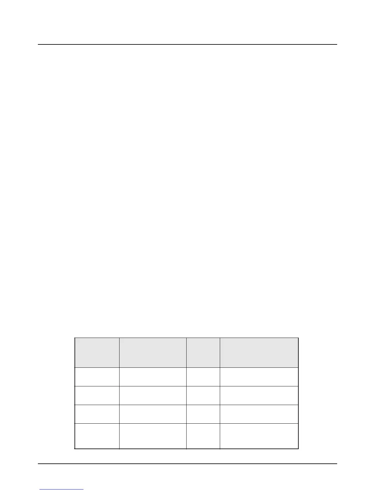
Table 8-3 lists the various fasteners by part number and description, followed by the torque values
and the location where used. Torque all fasteners to the recommended value when assembling the
radio.
Table 8-3. Fastener Torque Chart
Part Number Description
Repair
Torque
(in.-lbs.)
Where Used
N/A Hex nut, 7/16 6-8 Mini-UHF antenna
connector
03-10907A97 Screw, M3.5X30 10-12 Interconnect board (high-
power)
03-10911A11 Screw, machine M3X8 6-8 PA boards device
attachment
03-10943A10 Screw, machine M3X6 8-10 TO-39 heatsink
(PA, Q3804) (very low-, low-,
and mid-power)
 Loading...


