6881076C20-E February 3, 2003
Disassembly/Reassembly Procedures: Replacement Procedures 8-3
11. Remove the circuit board assembly from the housing.
12. Remove the keypad [6] from the housing assembly [7].
8.2.2.2 Models W4, W5, and W7
NOTE: For the following procedure, refer to Chapter 11: Exploded Views and Parts Lists, beginning
on
page 11-3, for the exploded view and associated parts list applicable to the model being
disassembled.
1. Unplug the microphone.
2. Remove the two front panel screws using a 2.5mm hex-key driver.
3. Disconnect the control cable on remote models.
4. Grasp the front panel firmly, and carefully unplug the control head assembly from the radio or
remote control head back housing.
5. Lay the control head face down on a clean, flat surface, being careful not to scratch or mar
the display.
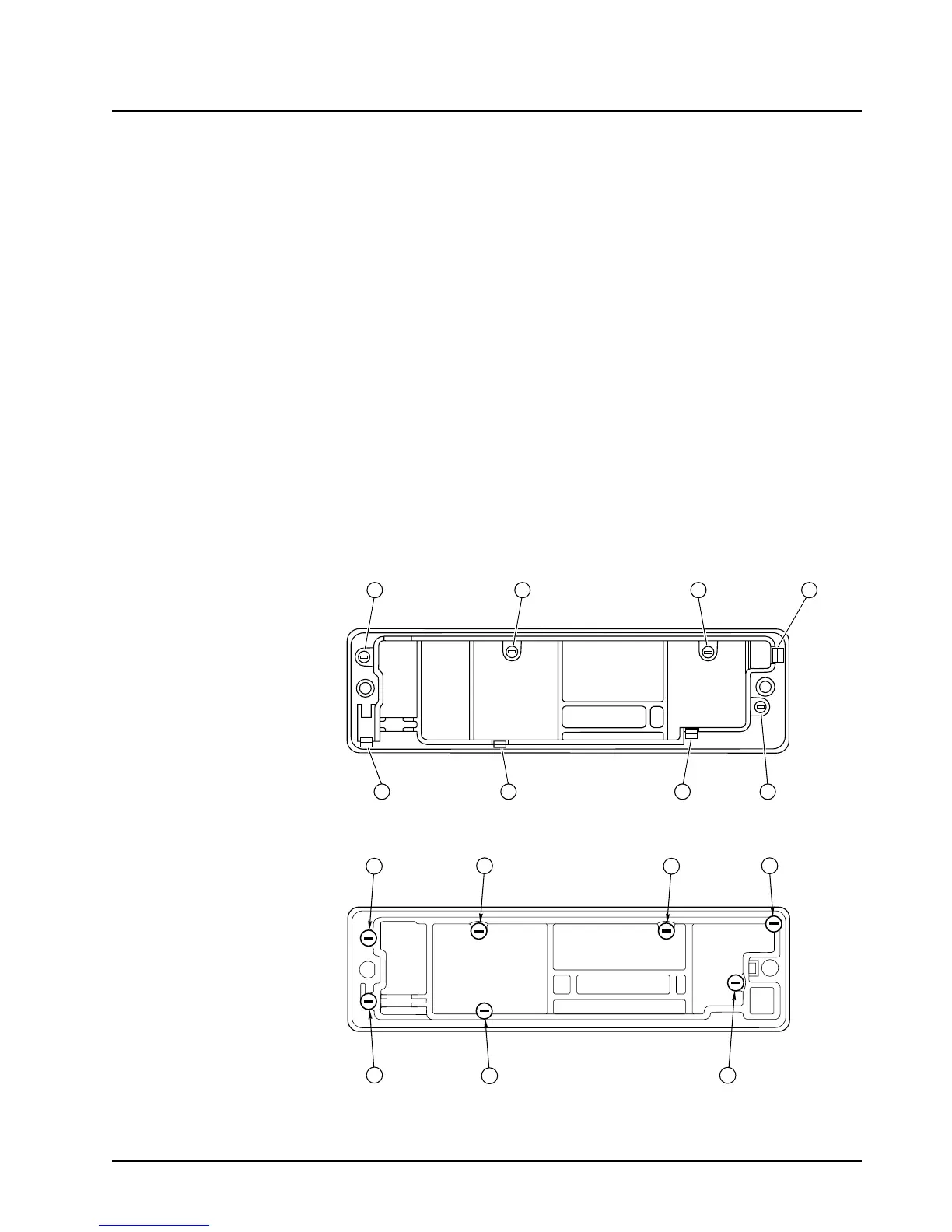
6. Using a Torx T10 driver, remove the control head screws:
- Model W4: four screws [callouts 5-8], as shown in
Figure 8-1.
The Model W4 has, in addition to the screws, four snap features [callouts 1-4], which are shown in
Figure 8-1.
- Model W5 and Model W7: seven screws, as shown in
Figure 8-2.
Figure 8-1. Model W4 Rotary Control Head Assembly Screw and Snap Sequence
Figure 8-2. Models W5 and W7 Pushbutton Control Head Assembly Screw Sequence
7 1
58
3
4
2 6
416
2
5
3
7
 Loading...


