6881076C20-E February 3, 2003
Basic Troubleshooting: Receiver Troubleshooting 9-9
9.6 Receiver Troubleshooting
The following table can help you troubleshoot problems that might occur in the receiver section of
your radio.
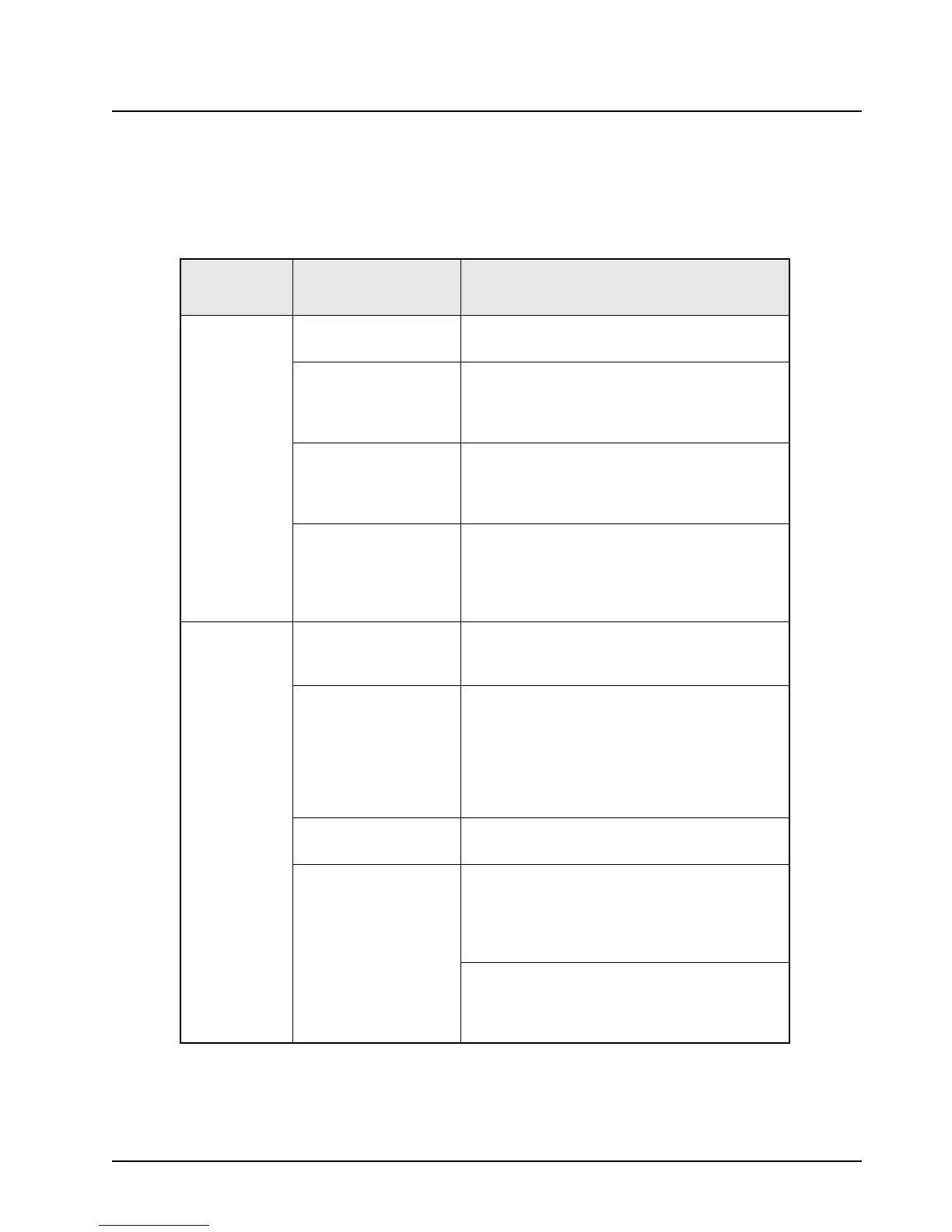
Table 9-6. Receiver Troubleshooting Chart
Symptom Possible Cause
Correction or Test (Measurements Taken
at Room Temperature)
Radio Dead,
Display Does
Not Light Up
Blown Fuse Check fuse in red lead of power cable (or green
lead if used.)
On/Off Switch (Control
Head)
Check for SWB+ at pin 31 of J502 on the
command board.
If not there, check for SWB+ at pin 21 of P502 on
the control head.
Regulators (Command
Board)
Check for 9.6 Vdc on pin 10 of J500 and +5V on
pin 1 of J500.
If not there, check for A+ at pin 30 of 502.
If OK, then replace the command board.
ASTRO Spectra Plus
VOCON Board
Check U410 pin 1 for 1.8 Vdc.
Check U411 pin 1 for 3.0 Vdc.
Check TP401 for 16.8 MHz.
If any of these is missing, replace the VOCON
board.
Radio Dead,
Display Lights
Up
Audio PA Circuit Check continuity of F500 on command board.
If open, check for speaker leads shorted to
ground, replace. F500 is located just above U450.
Synthesizer (RF Board) Check the synthesizer A Clock line (pin 19 of
J500).
If >3V, then go to the Synthesizer Troubleshooting
Chart on
page 9-12.
If <3V, check P501 pin 8.
If <3V there, replace control head; otherwise,
replace the command board.
RF Board Check pin 7 of P501 for 2.4 MHz.
If <3V, replace the RF board.
Regulators (Command
Board)
1. Check for 9.6 Vdc on pin 10 of J500 and +5 Vdc
on pin 1 of J500.
If not there, then check for A+ at pin 30 of P502
and SWB+ at pin 31 of J502.
If OK, replace the command board.
2. Check pin 38 of P501 for A+.
If not there, replace the command board.
Check pins 33, 34, 37 of P501 for 5 Vdc.
If not there, replace the command board.
 Loading...


