February 3, 2003 6881076C20-E
6-20 Radio Alignment Procedure: ASTRO Digital Spectra and Digital Spectra Plus Tuner Software
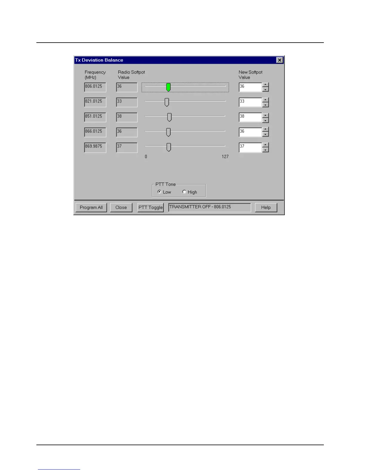
Figure 6-16. Transmit Deviation Balance (Compensation) Alignment Screen
6. Left-click the PTT Tone: Low button.
7. Left-click the PTT Toggle button on the screen to enable transmission. The screen indicates
whether the radio is transmitting. Wait approximately 5 seconds until the voltage shown on R-
2670, or the deviation shown on the 8901_ analyzer, stabilizes.
8. Measure and record the ac voltage value from the R-2670 analyzer or the deviation value
from the 8901_ series analyzer.
9. Left-click the PTT Tone: High button.
10. Adjust the softpot value until the measured deviation/voltage, when using the high tone, is
within +/- 1.5% of the value observed when using the low tone.
11. Repeat the above process for all frequencies.
12. Left-click the Program (Digital Spectra) or Program All (Digital Spectra Plus) button on the
screen to dekey the radio and save the tuned values.
13. Left-click the Close button on the screen to return to the Transmitter Alignments menu.
6.3.6 Transmit Deviation Limit Alignment
This alignment is required after replacing (or servicing) the VOCON board or the transceiver board.
This alignment procedure limits the modulation of a baseband signal. It is used for primary
modulation limiting.
This procedure needs to be performed at multiple frequencies to allow for proper alignment across
the entire RF band. The RF band is divided into frequency zones with a calibration point (value) in
each zone.
 Loading...


