Mounting and installation
Instructions for safe installation
Connection to the main system or to a system
add-on
Cable length - Item number:
0.3m - 30322355
1.5m - 30322359
3.2m - 30322358
6.5m - 30322357
10m - 30322356
Connection to the EDS bus
3130308311 - Is supplied with the EDS
communication module.
Instructions for safe installation
To prevent damage to the system components, consider the following during installation:
▪ Install the job computer where it is protected from dirt. You therefore avoid unintentional cleaning
of the job computer by the implement operator using a high-pressure cleaner.
▪ In the installed position, the plugs and the pressure compensation membrane must be facing to
the side.
▪ Fasten the job computer using four conducting fixing bolts on the chassis of the field sprayer. In
case of improper installation, the ESD discharges can cause malfunctions.
▪ All of the sockets and plugs that are not used must be protected from dust using suitable dust
protection caps.
▪ All of the plugs must be tightly sealed. This makes them waterproof.
▪ Do not use the system if some of its parts are damaged. Damaged parts can cause malfunctions
and lead to injuries. Replace damaged components or repair them if possible.
▪ Use only original components manufactured by Müller-Elektronik.
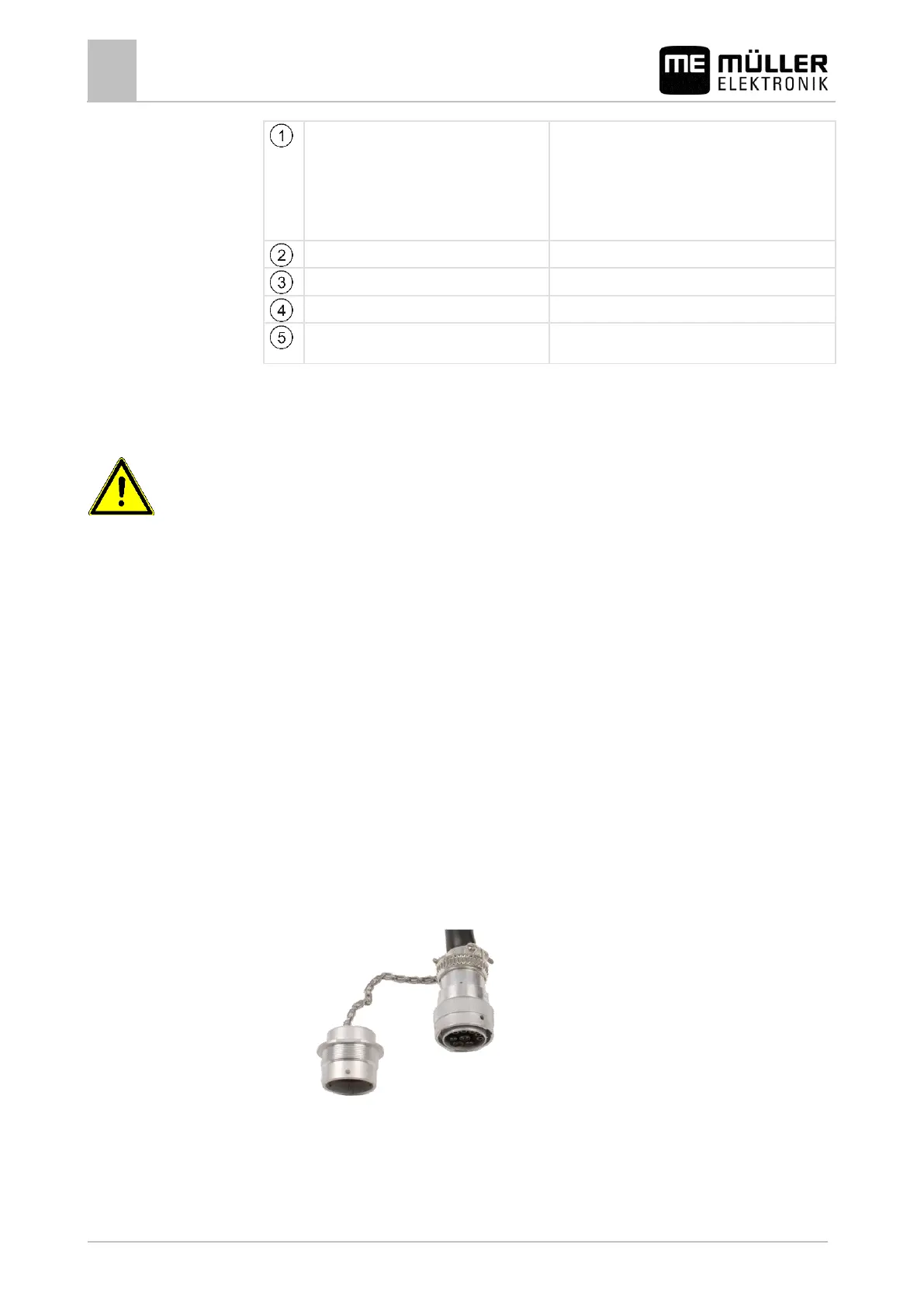
Connecting the job computer to the ISOBUS
To connect the job computer to the power supply and to the ISOBUS terminal, you have to connect
the ISOBUS cable to an ISOBUS power socket on the tractor.
This is how to connect the job computer to the ISOBUS:
1. Take the ISOBUS cable from the job computer.
2. Unscrew the dust protection cap.
⇨
3. Insert the ISOBUS connector into the ISOBUS power socket on the tractor.
4. Lock the connector. For basic vehicle harnesses from Müller-Elektronik, turn the connector
clockwise. For other ISOBUS basic vehicle harnesses, the procedure depends on the model.
⇨ The connector fits tightly.
 Loading...