Configuring the job computer
Configuring AIRTEC
5. Enter the password.
6. Restart the job computer.
Configuring AIRTEC
For the AIRTEC configuration, you only have to select the nozzle number for the mounted nozzle.
Wrong nozzle number
Damage to the plants
◦ Always enter the correct nozzle number.
1. Switch to the "AIRTEC" screen:
>
2. - Set the nozzle number.
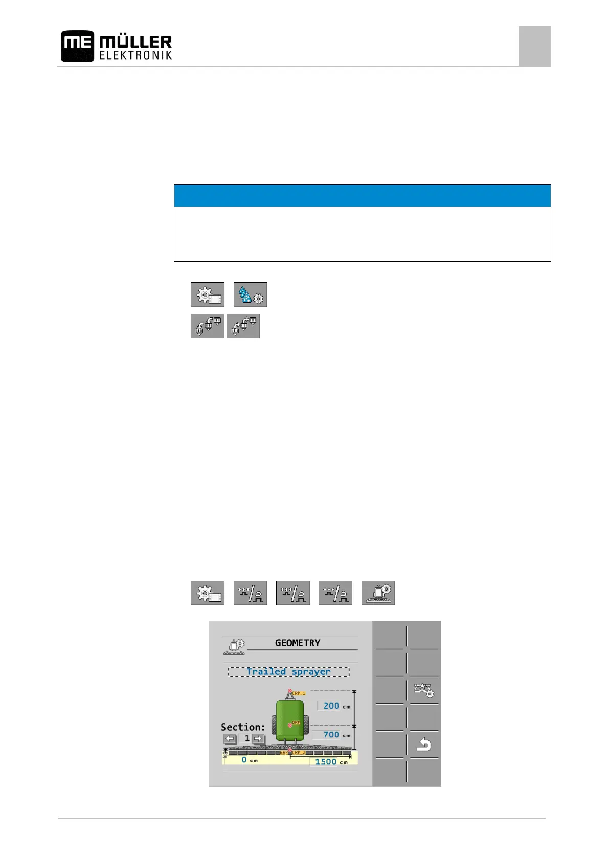
Entering the field sprayer geometry
Sprayer geometry is a set of parameters that describe the dimensions of your implement.
Setting the sprayer geometry lets the software know exactly how long and how wide the implement is
and where the individual sections are located.
Sprayer geometry parameters
When setting the sprayer geometry, you must measure the following distances:
▪ CRP – Attachment point, or point from which the measurements are taken. For self-propelled
sprayers, it can be the position of the GPS receiver, and for mounted and trailed sprayers, the
mounting or attachment point.
▪ DRP – Pivot point of the field sprayer, or point at which there is soil contact.
▪ ERP – Position of the nozzles.
1. Switch to the "GEOMETRY" screen:
> > > >
⇨ The following screen appears:
 Loading...