SECTION 2 -- CONTROLS, INSTRUMENTS AND OPERATION
2--75
Creeper Gears (where fitted)
For operations requiring extra low ground speeds,
reduction gear sets (creeper gears) are available.
The reduction gear set has the effect of reducing all
the ratios within the main transmission to provide an
additional twenty four gears in forward and reverse.
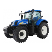
The creeper gears are selected by means of a rocker
switch (1) located on the right-hand control console.
With the engine running, clutch depressed and the
shuttle lever in neutral, apply and hold down the
tractor footbrakes. Momentarily depress the lower
part of the selector switch (1), Figure 121, to engage
the creeper gears.
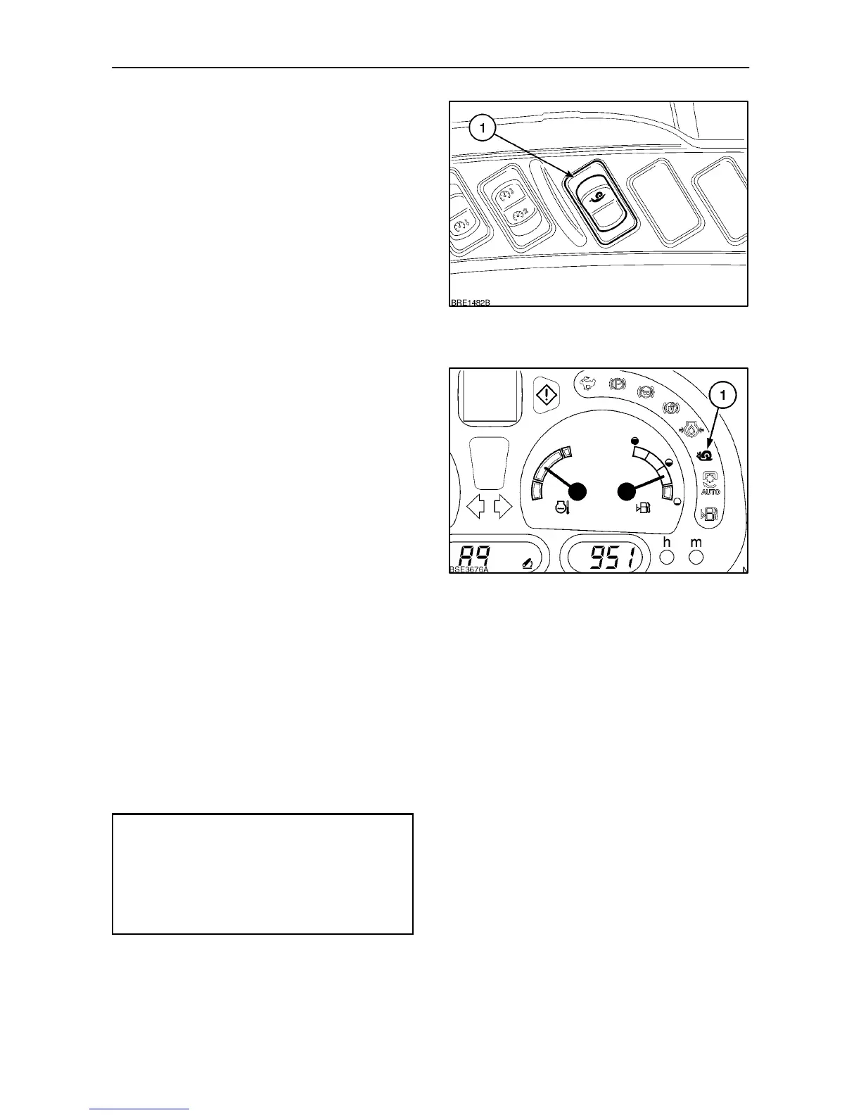
The creep speed symbol (1) Figure 122, will appear
in the Instrument panel.
To disengage creeper gears, repeat the above
procedure and depress the selector switch again.
The creep speed symbol will cease to illuminate.
IMPORTANT: The creeper gears offer very low
ground speeds. Do not use the low gearing
advantage to apply excessive draft loads to the
tractor.
121
122
Error Codes
Should a fault occur in the transmission controls,
causing the tractor to become disabled, an error
code will be displayed in the instrument panel. If this
should happen, contact your authorised dealer and
report the error code displayed.
There are a number of ’action reqired’ error codes
which can also appear in the Dot Matrix Display,
these are listed below.
Error
Code
Fault
P
Park brake on, release brake lever .
N
Place the shuttle lever in neutral.
C
Wheel speed too high for creeper gears.
CP
Depress clutch pedal to enable
transmission (restore drive).
T ransmission Calibration
Should transmission shifts become slow or jerky, the
clutches in the transmission may require
re--calibrating. Consult your authorised dealer.
 Loading...