SECTION 3 -- FIELD OPERATION
3--81
ADDITIONAL OIL SUPPLY FOR REMOTE
HYDRAULIC SERVICES
(Power Beyond Port, where fitted)
For implements or attachments requiring continuous
or high oil flows from the tractor hydraulic system,
provision is made to connect directly into the main
hydraulic circuit at the rear of the tractor.
To operate correctly the implement must be fitted
with a variable flow hydraulic system that will,
through a sensing line, control oil flow from the main
tractor hydraulic pump.
1
2
139
IMPORTANT: Before attempting to remove any
blanking plugs or attach pipework, switch OFF the
engine and ensure the areas around the plugs and
pipe connections are thoroughly clean to prevent
contamination of the tractor hydraulic system.
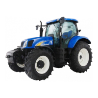
P -- Pressure Line (1)
To connect the implement pressure line, remove the
plug (1) from the external services ’power beyond’
port below the remote valve manifold. Using a
suitable connector, M22 x 1.5/15.5 (ISO 6149),
attach the implement supply line to this port. With the
implement control valve in neutral, a low standby
pressure of 21 to 24 bar (305 to 348 lbf. in.) will be
maintained in the pressure line connected to this
port.
140
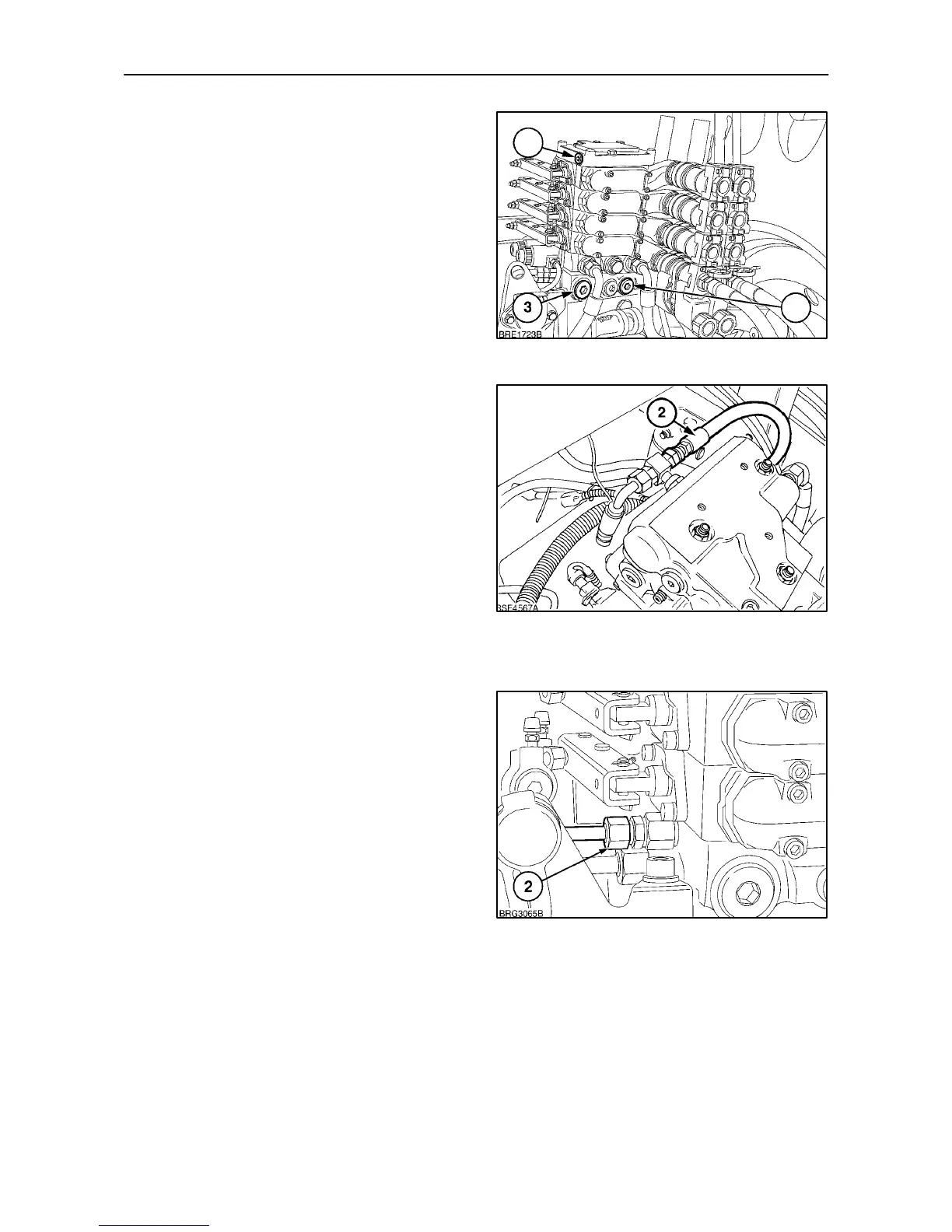
LS -- Load Sensing (LS) Line (2)
Connect the sensing line from the M12 x 1.5/11.5
(ISO 6149) port (2), to the implement control valve.
It is the sensing line which generates and controls the
oil pressure and flow from the tractor hydraulic pump.
When an implement control valve is operated, the
low standby pressure from port ’P’, is diverted down
the sensing line to ’switch on’ the tractor hydraulic
pump. In operation, the load sensing line constantly
monitors pressure and flow to ensure supply never
exceeds demand.
LS Port Location (2)
1. Figure 139, with mechanically operated remote
valves and Electronic Draft Control.
2. Figure 140, with electronically operated remote
valves and Electronic Draft Control.
3. Figure 141, with mechanically operated remote
valves and Mechanical Draft Control.
141
 Loading...