SECTION 2 -- CONTROLS, INSTRUMENTS AND OPERATION
2--21
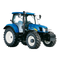
ELECTRICAL POWER CONNECTORS
INTERNAL POWER CONNECTORS
Depending on tractor specification there are a
number of electrical power connectors provided for
various applications. These are as follows:
1. 8 amp Screw terminals. The red terminal is
positive, the black terminal negative.
2. 7 Pole Din/ISO implement socket (with radar
option only) provides the information below.
3. 30 amp ISO/JD implement power socket.
Provides constant and key--start switched live
feeds.
34
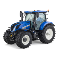
7 Pole Din/ISO Implement Socket Connectors
Pin 1. True ground speed. (Radar Sensed)
Pin 2. Theoretical ground speed.
(Wheel Sensed)
Pin 3. Rear P.T.O. speed.
Pin 4. Rear 3--point hitch, in work/out of work.
Pin 5. Not used
Pin 6. 5 amp power supply.
Pin 7. Common ground connection.
35
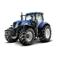
4. Cigarette lighter/auxiliary power socket for
mobile telephone or cooler box (where fitted).
5. 8 amp Single pole auxiliary power socket. Live
with key--start in ’on’ position.
IMPORTANT: To ensure that terminals and
connecting cables do not get excessively hot when
loaded with near maximum current it is important to
make secure, tight connections to prevent
overheating and damage. Ensure that equipment is
connected to the terminals with cables of suitable
gauge and insulation thickness and fitted with
appropriate terminal connectors.
36

 Loading...