ENGLISH – 11
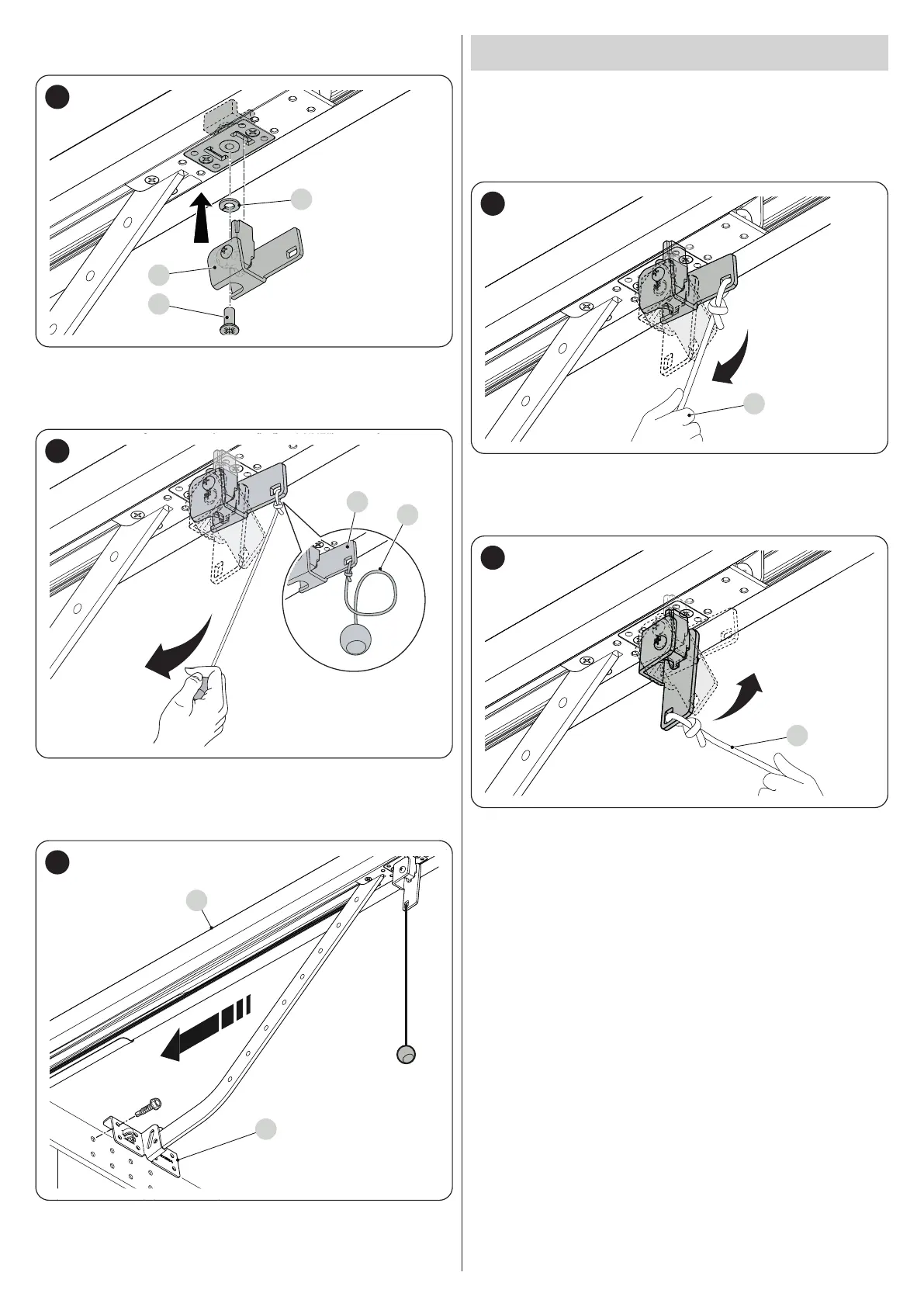
25. assemble the unlocking system (S) by tightening the screw (V) and
placing the spring washer (R) in between (“Figure 22")
S
V
R
22
26. fasten the cord (C) and the relevant unlocking ball to the unlocking
system (S)
27. with the door closed, pull the cord (C) to release the carriage (“Fig
-
ure 23")
23
28. slide the motor carriage until the door mounting bracket (K) on the
upper edge of the door lies exactly perpendicular to the guide (A)
29. fasten the bracket (K) using the screws and rivets suited to the door
material and the force required to move the door itself (“Figure 24")
24
3.7 MANUALLY UNLOCKING AND LOCKING THE
GEARMOTOR
The gearmotor is equipped with a mechanical unlocking device that can
be used to open and close the door manually.
These manual operations should only be performed in case of a power
outage, malfunctions or during the installation phases.
To unlock the device:
1. pull the releasing cord (A) (“Figure 25")
A
25
2. the door can now be moved manually to the desired position.
To lock the device:
1. pull the releasing cord (A) (“Figure 26")
A
26
2. manually move the door to align the lower part of the motor car-
riage with the upper part so that it slots into place.
 Loading...


