ENGLISH – 33
TROUBLESHOOTING GUIDE
9
9 TROUBLESHOOTING GUIDE
9.1 TROUBLESHOOTING
The table below contains useful instructions to resolve any malfunctions or errors that may occur during installation or in case of a fault.
Table 23
TROUBLESHOOTING
Problems Recommended checks
The radio transmitter does not control the
automation and the LED on the transmitter
fails to light up
Check whether the transmitter batteries are exhausted and replace them if necessary.
The radio transmitter does not control the
automation but the LED on the transmitter
lights up
Check whether the transmitter has been memorised correctly in the radio receiver.
No manoeuvre is commanded and the “OK”
LED fails to ash
Check that the gearmotor is being powered with the mains voltage
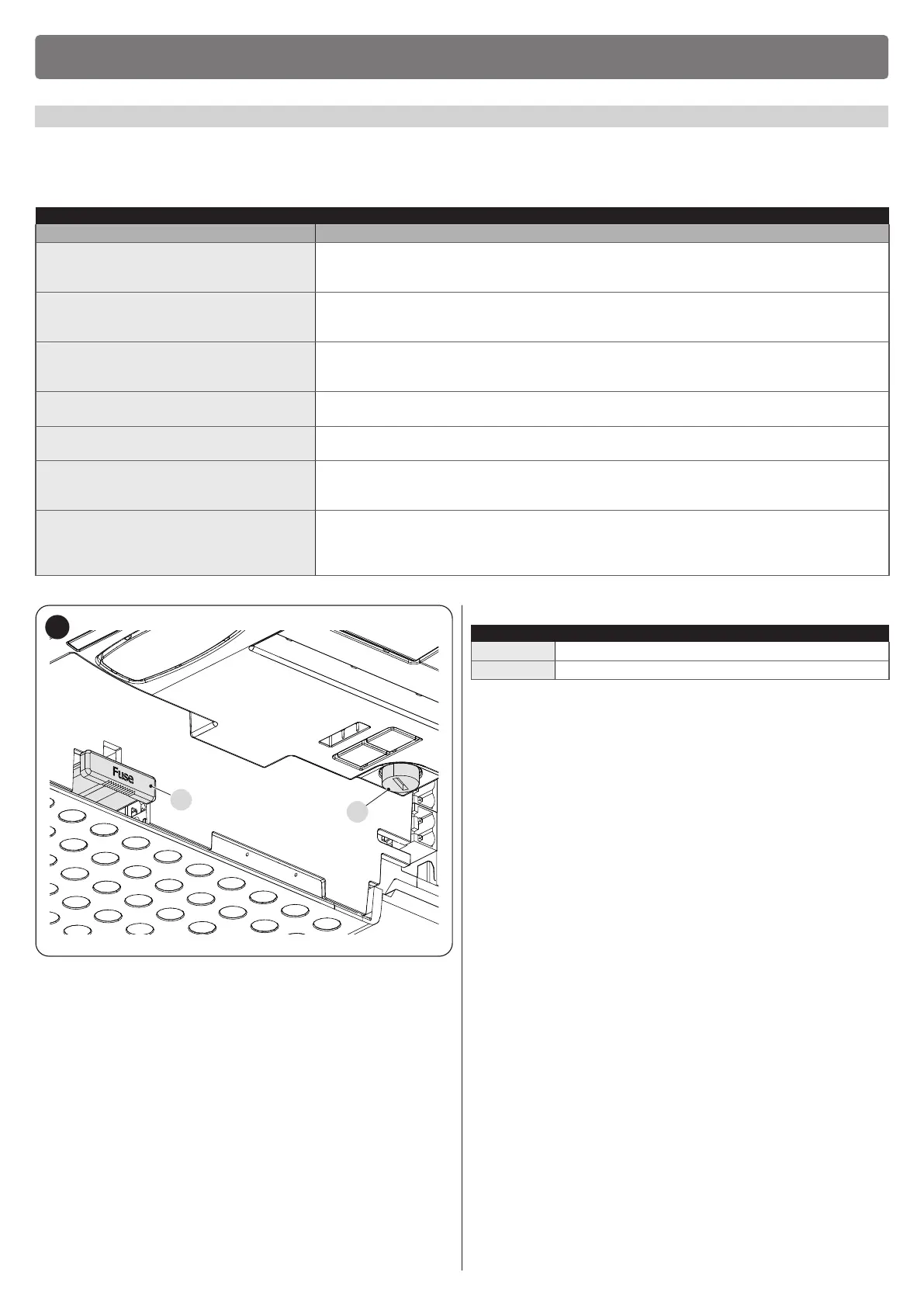
Check whether fuses F1 and F2 are blown; if they are, identify the cause of the failure then replace the
fuses with others having the same current rating and characteristics.
No manoeuvre starts and the warning light
is off
Check that the command is actually received. If the command reaches the SbS input, the “OK” LED
must light up; if instead the radio transmitter is used, the “OK” LED must emit two quick ashes.
No manoeuvre starts and the warning light
ashes a few times
Count the number of ashes and check the corresponding value in “Signalling through warning
light”.
The manoeuvre starts but is immediately
followed by a reverse run
The selected force could be too low for this type of automation. Check whether there are any obstacles
and increase the force if necessary.
Check whether a safety device connected to the Stop input has tripped.
The manoeuvre is completed correctly but
the warning light does not work
Make sure that there is voltage on the warning light’s FLASH terminal during the manoeuvre (being
intermittent, the voltage value is not signicant: roughly 10–30 Vc); if there is voltage, the problem is
due to the lamp, which must be replaced with one having the same characteristics; if there is no voltage,
there may have been an overload on the FLASH output. Check that the cable has not short-circuited.
F2
F1
48
Table 24
CHARACTERISTICS OF FUSES F1 AND F2
F1 Control unit fuse = 2 A delayed
F2 Mains power supply fuse = 1.6 A delayed
 Loading...


