ENGLISH – 7
3.5 PRE-INSTALLATION WORKS
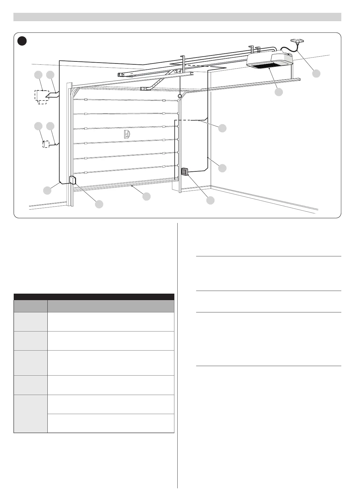
The gure shows an example of an automation system, constructed using Nice components.
A
1
2
B
3
C
4D
5E
B
3
5
A Gearmotor
B Photocells
C Main edge
D Key selector
E Warning light with incorporated antenna
The above-mentioned components are positioned according to a typical
standard layout. Using the layout shown in “Figure 5” for reference, dene
the approximate position in which each component of the system will be
installed.
Table 4
TECHNICAL SPECIFICATIONS OF ELECTRICAL CABLES
Identication
no.
Cable characteristics
1
GEARMOTOR POWER SUPPLY cable
1 cable 3 x 1.5 mm
2
Maximum length 30 m [note 1]
2
MAIN EDGE cable
1 cable 2 x 0.5 mm
2
Maximum length 20 m
3
PHOTOCELL cable
2 x 0.7 mm
2
BlueBus
4 x 0.5 mm
2
standard
Maximum length 30 m
4
KEY SELECTOR cable
2 cables 2 x 0.5 mm
2
[note 2]
Maximum length 50 m
5
WARNING LIGHT cable
1 cable 2 x 0.5 mm
2
Maximum length 20 m
ANTENNA cable
1 x RG58-type shielded cable
Maximum length 10 m; recommended < 5 m
Note 1 If the power supply cable is longer than 30 m, a cable with larger
cross-sectional area (3 x 2.5 mm
2
) must be used and a safety
earthing system must be installed near the automation.
Note 2 These two cables can be replaced by a single 4 x 0.5 mm
2
cable.
a
Before proceeding with the installation, prepare the re-
quired electrical cables by referring to “Figure 5” and to
that stated in the “TECHNICAL SPECIFICATIONS” chap-
ter (page 59).
a
The cables used must be suited to the type of environ-
ment of the installation site.
a
When laying the pipes for routing the electrical cables,
take into account that any water deposits in the junction
boxes may cause the connection pipes to form conden-
sate inside the control unit, thus damaging the electronic
circuits.
“Figure 6” shows typical installations for a protruding and non-protruding
overhead door.
m
For installation on protruding and non-protruding doors,
accessory SPA5 is required.
 Loading...


