ENGLISH – 13
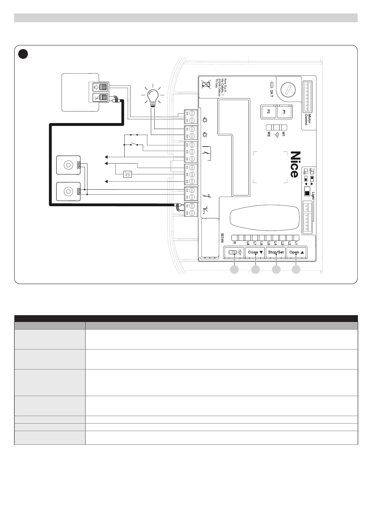
4.2 WIRING DIAGRAM AND DESCRIPTION OF CONNECTIONS
4.2.1 WIRING DIAGRAM
TX
Bluebus
RX
Bluebus
NC
NO
SBS
24V
GND
PHOTO
12V
STOP
FLASH
AERIAL
24V
+ -
12V OSE
Bluebus
Aerial
GND
Stop
Flash
Photo
OGI
SbS
29
4.2.2 DESCRIPTION OF CONNECTIONS
Table 5
ELECTRICAL CONNECTIONS
Terminals Description
FLASH
(output limited to 10 W – 24
V)
This output is programmed by default to command a Warning light. The output can be programmed (refer to the “
PROGRAMMING THE CONTROL UNIT” chapter). The output conguration modes are listed in “Table 37”.
OGI
(output limited to 10 W – 24
V)
This output is programmed by default to command the Open Gate Indicator. The output can be programmed (refer to the
“PROGRAMMING THE CONTROL UNIT” chapter). The output conguration modes are listed in “Table 38”.
BLUEBUS
This terminal can be used to connect compatible devices, which are all connected in parallel with only two wires carrying
both the electric power and communication signals.
For further information on the BlueBUS, refer to the “Addressing of devices connected with the BlueBUS system”
paragraph.
STOP
Input for the devices that block or, if necessary, stop the manoeuvre under way. With suitable arrangements, “Normally
Closed” or “Normally Open” contacts, or xed resistor or optical devices can be connected to the input (refer to the “STOP
input” paragraph).
SbS Input for devices that control the movement in Step-by-Step mode; it is possible to connect “Normally Open” contacts.
PHOTO Input for safety devices: it is possible to connect "Normally Closed" contacts to this input.
ANTENNA
Antenna connection input for radio receiver; the antenna is incorporated in the warning light; alternatively, an external
antenna can be used.
 Loading...


