ENGLISH – 31
“Table 22” illustrates the signals emitted by LEDs W1 and W2 and their meaning.
Table 22
WI-FI MODULE LED STATUS
WiFi /BT (W2) Power/Sys (W1) LEDs W1 and W2 status Description
Lit green Lit green Fixed
The integrated module is in its normal operating status and a
smartphone is connected.
Lit green Green, 8 quick ashes Temporary (a few seconds) The module has undergone an “Identify” action by the user.
Flashing green Lit green Fixed
The module is awaiting to receive the Wi-Fi network
conguration from the user. Use the app to congure the
module.
Lit orange Lit green Fixed
The module is in its normal operating status and no
smartphone is connected.
Flashing orange Steady green Temporary (a few seconds)
The module is conguring the Wi-Fi connection. If
permanent, it means that a problem occurred during the
Wi-Fi conguration.
OFF Steady green Fixed
The module cannot be congured because 30 minutes
have passed from the switching on (only with a module
that has not yet been congured). To congure the module,
disconnect the power supply to the control unit and then
restore it.
OFF Flashing orange Temporary (roughly 1 minute)
The module is updating. Wait for the operation to be
completed. If the operation is not completed correctly, the
module automatically restarts after 5 minutes.
Flashing red OFF Transitory
The module has detected the pressing of the reset button
when the control unit was switched on.
Steady red Lit green Fixed
The module cannot connect to the domestic Wi-Fi network
or is unable to connect to the Nice cloud.
8.5.2 BIDI-WI-FI INTERFACE
To connect the BiDi-Wi-Fi interface:
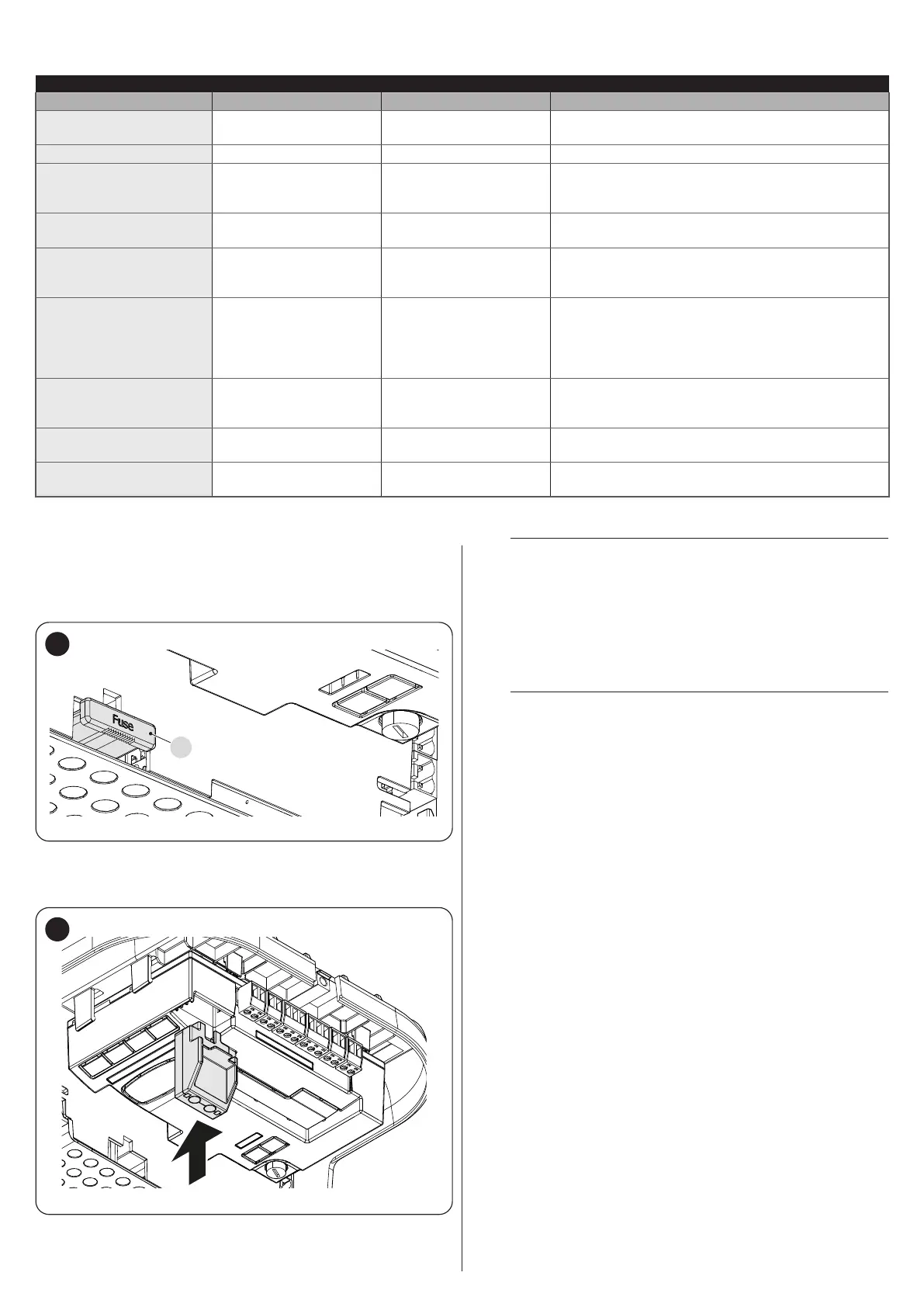
1. Disconnect the power supply to the control unit by removing the
fuse F2 and, if necessary, the emergency power supply
F2
44
2. Verify that all the control unit LEDs are switched off before pro-
ceeding
Insert the BiDi-Wi-Fi interface in the BUS T4 connector of the control unit
45
l
Warning! If it is not correctly inserted, the BiDi-Wi-Fi in-
terface could get damaged or permanently damage the
control unit.
3. Insert fuse F2 to switch the control unit on again
4. Wait for the Date LED to start ashing
5. Congure the interface through the app
6. Wait until the Date LED switches on and the green light stays
steady lit. At this point the conguration will have been completed.
l
For further details relative to the functions linked
to the BiDi-Wi-Fi interface, consult the website
www.niceforyou.com.
 Loading...


