42 – ENGLISH
10.1.8 ELECTRIC LOCK
The OGI output is by default enabled for the OGI (Open Gate Indicator)
function, but can be programmed for controlling an electric lock (refer to
the “Level 2 programming (adjustable parameters)” paragraph on
page 28).
At the start of the opening movement, the output is activated for 2 sec
-
onds, while during the closing manoeuvre it is not activated, therefore the
electric lock must reset mechanically.
The output cannot control the electric lock directly, but only loads of 24 V
c 10W.
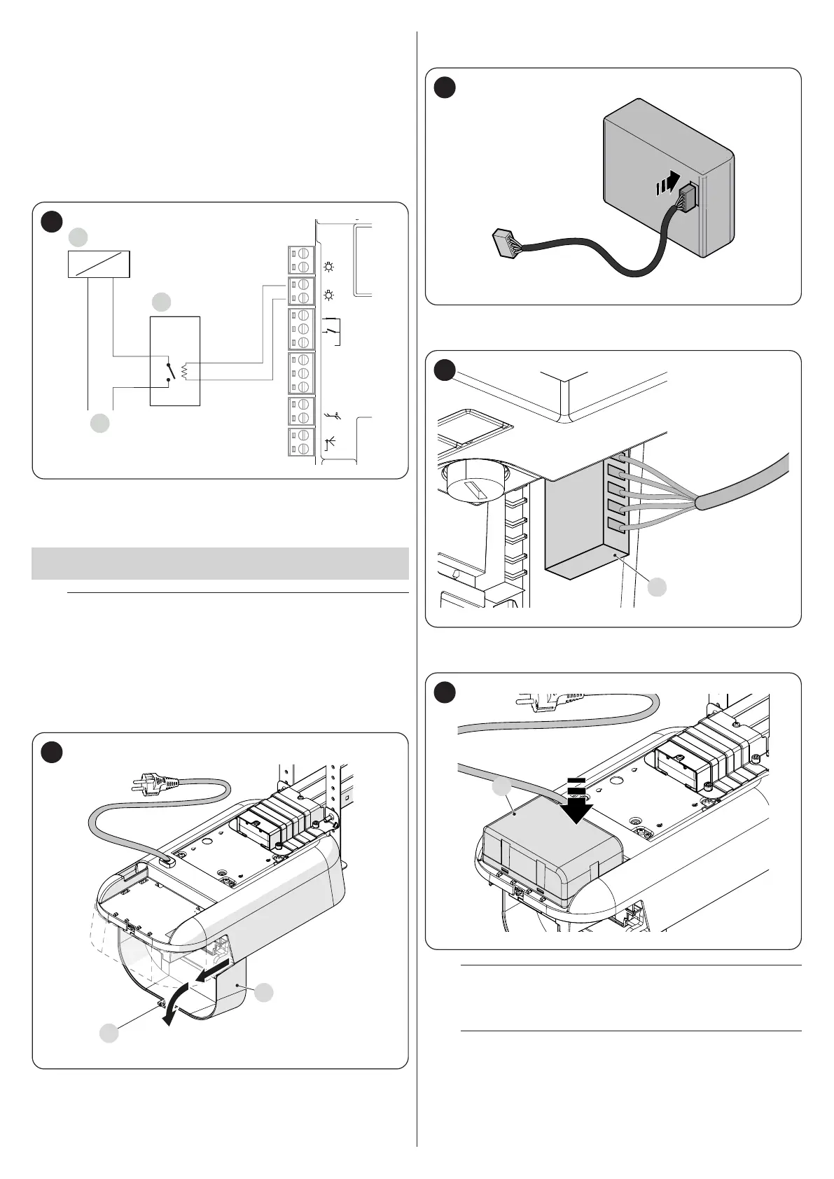
The output must be interfaced with a relay, as shown in the gure.
A
C
B
24V
+ -
12V OSE
Bluebus
Aerial
GND
Stop
Flash
Photo
OGI
SbS
57
A Electric lock
B 24 V c support relay
C Electric lock power supply
10.2 CONNECTING AND INSTALLING THE
EMERGENCY POWER SUPPLY
f
The electrical connection of the battery to the control unit
must be made only after completing all the installation
and programming stages, as the battery is an emergency
power supply.
To install and connect the battery:
1. loosen the screw (A)
2. pull the cover (B) slightly outwards and turn it downwards (“Figure
58")
A
B
58
3. connect the appropriate cable to the connector of the back-up bat-
tery (PS124) (“Figure 59")
59
4. insert the relative connector (C) on the connector emerging from
the motor compartment (“Figure 60")
C
60
5. insert the back-up battery (D) into its housing inside the motor body
(“Figure 61").
D
61
a
Warning! The installation of the back-up battery is advis-
able and useful when the stand-by mode must be acti-
vated.
a
Warning! In the SPIDER1200BLW model, if the back-up
battery is used, the “All” stand-by function must not be
used.
 Loading...


