ENGLISH – 15
Table 6
PHOTOCELL ADDRESSES
Photocell
Position of the
jumpers
FOTO (PHOTO)
Internal photocell h = 50 cm activated during
the closing phase (stops and reverses the
gate’s movement)
FOTO II (PHOTO II)
Internal photocell h = 100 cm activated during
the closing phase (stops and reverses the
gate’s movement)
FOTO 1 (PHOTO 1)
External photocell h = 50 cm triggered on
closing and opening (stops and restarts on
opening when the photocell disengages)
FOTO 1 II (PHOTO 1 II)
External photocell h = 100 cm triggered on
closing and opening (stops and restarts on
opening when the photocell disengages)
FOTO 2 (PHOTO 2)
Internal photocell activated during the opening
phase
FOTO 2 II (PHOTO 2 II)
Internal photocell activated during the opening
phase
FOTO 3 (PHOTO 3)
Photocell triggered on opening and closing
FA1
Photocell for opening command
(cut jumper A on the back of the TX and RX
boards)
FA2
Photocell for opening command
(cut jumper A on the back of the TX and RX
boards)
4.3.1 FT210B PHOTOSENSOR
The FT210B photosensor combines in a single device a force limiting sys-
tem (type C, in accordance with the EN12453 standard) and a presence
sensor that detects obstacles on the line of sight between the TX transmit
-
ter and RX receiver (type D, in accordance with the EN12453 standard). In
the FT210B photosensor, the signals regarding the status of the sensitive
edge are sent through the photocell range, integrating the 2 systems in a
single device. The transmitting element located on the moving leaf is bat
-
tery-powered, which eliminates visually unpleasant connection systems;
special circuits reduce battery consumption, ensuring up to 15 years’ life
(see estimation details in the product’s instructions).
A single FT210B device combined with a sensitive edge (TCB65, for ex
-
ample) allows for attaining the level of safety of the “primary edge” required
by the EN12453 standard for all “types of use” and “types of activation”.
The FT210B photosensor combined with the “resistive” sensitive edges
(8.2 kΩ) is safe against faults (category 3 pursuant to the EN 13849-1
standard). It is equipped with a special anti-collision circuit to prevent inter
-
ference with other detectors, even not synchronised, and allows for adding
other photocells; for example, in case of transit of heavy vehicles, where a
second photocell is normally positioned 1 m above the ground.
l
Consult the FT210B instruction manual for further infor-
mation on the connection and addressing methods.
FINAL CHECKS AND START-UP
5
5 FINAL CHECKS AND START-UP
It is advisable to position the leaf approximately halfway along its path
before starting the automation check and start-up phases, so that the leaf
is free to open and close.
5.1 POWER SUPPLY CONNECTION
a
The power supply connections must only be made by
qualied and experienced personnel possessing the nec-
essary requirements and in full conformity to the laws,
regulations and standards in force.
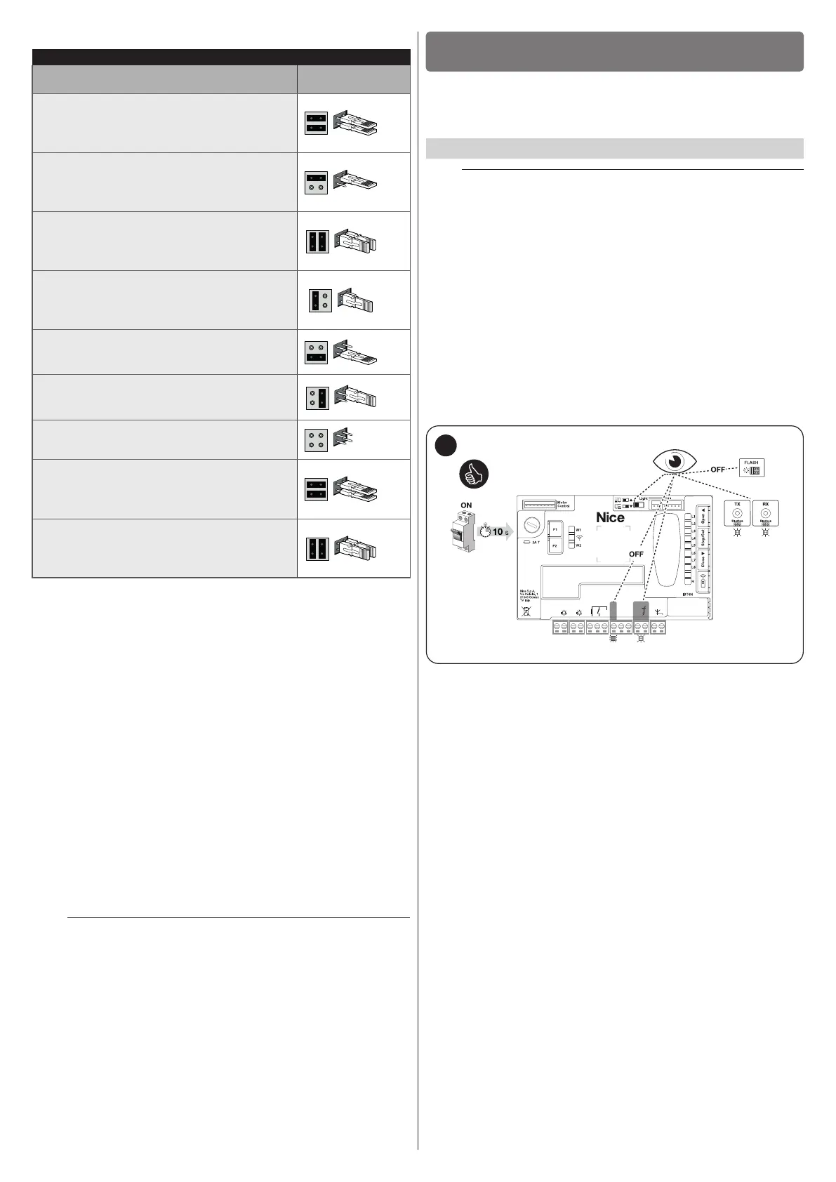
When starting up the product for the rst time, we suggest running a few
simple checks:
1. verify that the BlueBUS LED emits a series of 4 RED ashes to indi
-
cate the initial start-up and the lack of conguration.
2. make sure that the LEDs on the photocells (both the TX and RX)
also ash; the type of ashing is irrelevant, since it depends on
other factors.
3. check that the warning light connected to the FLASH output is off.
4. check that the courtesy light is off. The presence of 4 red ashes on
the cover must be regarded as normal.
5. verify that the selector is properly positioned: the cursor must be
positioned (by default) on the left.
24V
+ -
12V OSE
Bluebus
Aerial
GND
Stop
Flash
Photo
OGI
SbS
31
If the above conditions are not satised, immediately switch off the power
supply to the control unit and carefully check the electrical connections.
Further useful information on fault search and diagnosis is included in the
“Troubleshooting” paragraph (page 33).
 Loading...


