38 – ENGLISH
FURTHER DETAILS (Accessories)
10
10 FURTHER DETAILS (Accessories)
10.1 ADDING OR REMOVING DEVICES
Once the automation has been assembled, it is possible to add or remove
devices at any time. In particular, various types of devices can be connect
-
ed to the “BlueBUS” and “STOP” inputs, as described in the following
paragraphs.
m
After having added or removed devices, these must be
learned as described in the “Learning of other devices”
paragraph.
a
Warning! To add or remove an expansion board, it is rst
necessary to switch off the power supply.
10.1.1 BLUEBUS
BlueBus is a technology that allows for connecting compatible devices
using only two wires that carry both the power supply and the communi
-
cation signals. All the devices are connected in parallel on the 2 wires of
the BlueBus itself. It is not necessary to observe any polarity; each device
is individually recognised because a unique address is assigned to it dur
-
ing the installation.
The following devices can be connected to the BlueBUS: photocells, safe
-
ty devices, control buttons, signalling lights, etc. The control unit recognis-
es all the connected devices individually through an appropriate learning
phase, and can detect all possible anomalies with absolute precision.
For this reason, whenever a device is connected to or removed from Blue
-
BUS, the learning phase must be carried out on the control unit, as de-
scribed in the “Learning of other devices” paragraph.
10.1.2 STOP INPUT
STOP is the input that causes the immediate interruption of the manoeu-
vre, followed by a brief inversion. Devices with normally open (“NO”) and
normally closed (“NC”) contacts, optical devices (“Opto Sensors”) or de
-
vices with 8.2 kΩ xed resistor output (such as sensitive edges) can be
connected to this input.
During the device learning phase, the control unit recognises the type of
device connected to the STOP input and later, during normal use of the
automation, the control unit commands a STOP when it senses a change
with respect to the acquired situation.
Multiple devices, even of different types, can be connected to the STOP
input if suitable arrangements are made:
– Any number of NO devices can be connected to each other in parallel.
– Any number of NC devices can be connected to each other in series.
– Two devices with 8.2 kΩ xed resistor output can be connected in par
-
allel; if there are more than 2 devices then they must all be connected in
cascade, with a single 8.2 kΩ terminating resistor.
– It is possible to combine two NO and NC contacts by placing them
in parallel, while also mounting a 8.2 kΩ resistor in series with the NC
contact (this also allows for combining 3 devices: NA, NC and 8.2 kΩ).
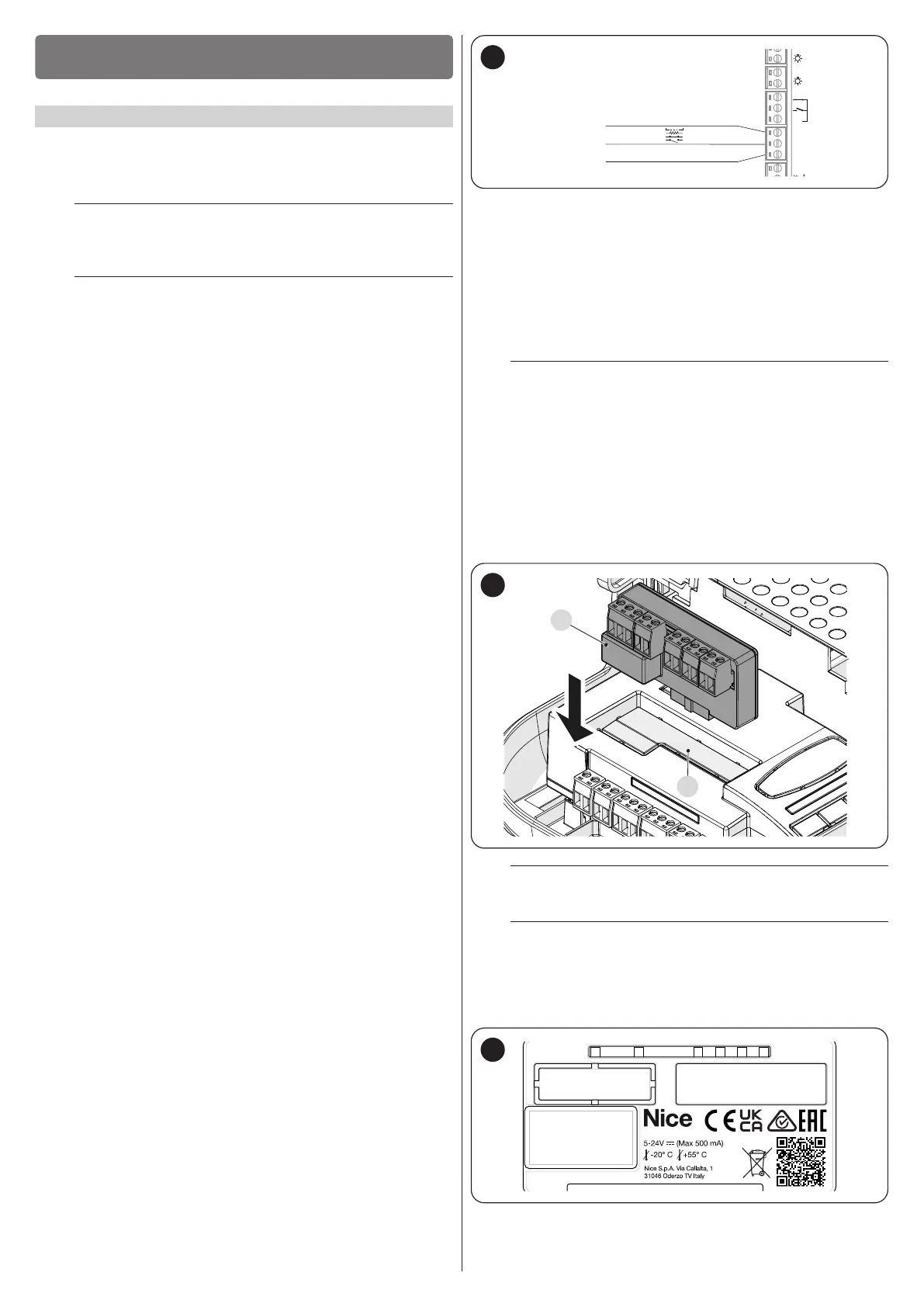
– To connect an optical device, refer to the diagram shown in “Figure 50”.
The maximum current supplied on the 12 VDC line is 15 mA.
OPTICAL SENSOR
(max 15mA)
STOP (-)
SIGNAL
12 V (+)
24V
12V OSE
Bluebus
GND
Stop
Flash
Photo
OGI
SbS
50
10.1.3 I/O EXPANSION BOARD (OPTIONAL ACCESSORY)
The control unit is congured for housing various versions of I/O expansion
boards which make available additional inputs and outputs. Each addition
-
al input/output can be personalised as if it were a physical input/output of
the control unit.
Whenever an expansion board is inserted or removed, the “device ac
-
quisition” procedure must be carried out: if this is not done, the motor’s
movement will remain limited to the “hold-to-run” function.
m
The addition or removal of expansion boards must always
be carried out without power supply (by removing both
fuse F2 and, if present, the battery pack).
To add the expansion board:
1. disconnect the control unit from the power supply
2. remove the pre-detachment element (A)
3. t the expansion (B) into the appropriate slot on the control unit
circuit board.
4. power the control unit
5. repeat the learning procedure for the devices as described in the
paragraph “Learning of other devices”.
B
A
51
a
Warning! On some models the expansion board is sup-
plied as a standard feature
a
Warning! Verify the electrical consumption of the control
unit and of the expansion board. Do not exceed the max-
imum allowed power.
The specic manual of the expansion board is available on-line. Use your
smartphone to frame the QR Code of the board.
52
 Loading...


