40 – ENGLISH
10.1.6 RELAY PHOTOCELLS WITH PHOTOTEST FUNCTION
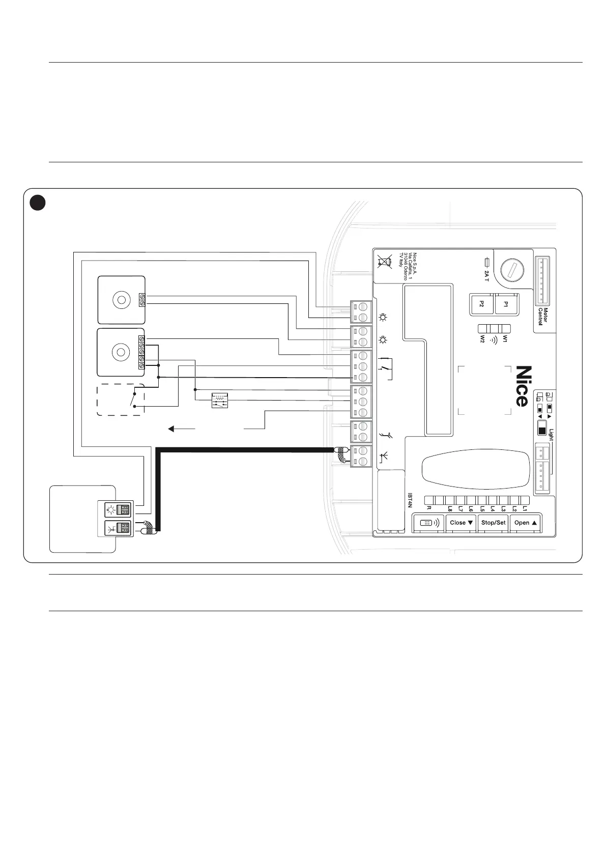
The control unit features a PHOTOTEST function which increases the reliability of the safety devices, enabling it to be classied in Category 2 in accord-
ance with the EN 13849-1 standard regarding the combination of the control unit and safety photocells.
a
Warning! To activate the PHOTOTEST function, it is necessary to modify the programming of the OGI output (refer to the “
Level 2 programming (adjustable parameters)“ chapter on page 28).
Whenever a manoeuvre is started, all safety devices involved are checked and only if everything operates correctly will the manoeuvre start.
Should the test fail (photocell blinded by the sun, cables short-circuited, etc.), the fault is identied and the manoeuvre is disabled.
Connect the photocells as shown in “Figure 55”.
Wiring diagram with relay photocells with PHOTOTEST
l
All images of the accessories are included purely for illustration purposes.
TX
- +
RX
NO
SbS
+ 12V - OSE
OSE
8k2
NC
NO
NC
C
NO
-
+
FLASH
AERIAL
24V
+ -
12V OSE
Bluebus
Aerial
GND
Stop
Flash
Photo
OGI
SbS
55
m
If 2 pairs of photocells are used that interfere with one another, it is necessary to activate the “synchronisation” as described
in the photocell instruction manual.
m
In any devices of the automation are replaced, added or removed, it is necessary to run the learning procedure (see the “
Manual programming of the door opening and closing positions” chapter on page 16).
 Loading...


