ENGLISH – 39
Table 30
EXPANSION BOARD
Product Description Input characteristics Output characteristics
MLAE44
4 Input
4 Output
IN 3 = dry contact (COM – IN3)
IN 4 = dry contact (COM – IN4)
IN 5 = dry contact (COM – IN5)
IN 6 = dry contact (COM – IN6)
OUT3 = Open Drain (max 10W = 24V - 0.4A)
OUT4 = Open Drain (max 10W = 24V - 0.4A)
OUT5 = Open Drain (max 10W = 24V - 0.4A)
OUT6 = Open Drain (max 10W = 24V - 0.4A)
MLAE22
2 Input
2 Output
IN 3 = dry contact (COM – IN3)
IN 4 = dry contact (COM – IN4)
OUT3 = Open Drain (max 10W = 24V - 0.4A)
OUT4 = dry contact with relay in exchange (230VAc – 5A)
MLAE21
2 Input
1 Output
IN 3 = dry contact (COM – IN3)
IN 4 = dry contact (COM – IN4)
OUT3 = Open Drain (max 10W = 24V - 0.4A)
10.1.4 LEARNING OF OTHER DEVICES
Normally the learning of devices connected to “BlueBus” and the “STOP”
input takes place during the installation stage; however, if new devices are
added or old ones removed, the learning process can be redone.
-
12V OSE
Bluebus
Aerial
GND
Stop
53
To do this:
1. simultaneously press and hold the
f
and
g
but-
tons
2. release the buttons when LEDs “L1” and “L2” start ashing rapidly
(after roughly 3 seconds)
3. wait a few seconds until the control unit has completed the device
learning phase
4. at the end of this phase, the “Stop” LED must be lit, LEDs “L1” and
“L2” must switch off, while LEDs “L1…L8” will switch on depend
-
ing on the status of the ON-OFF functions they represent.
m
After having added or removed devices, the automation
test must be carried out again as specied in the “Test-
ing” paragraph.
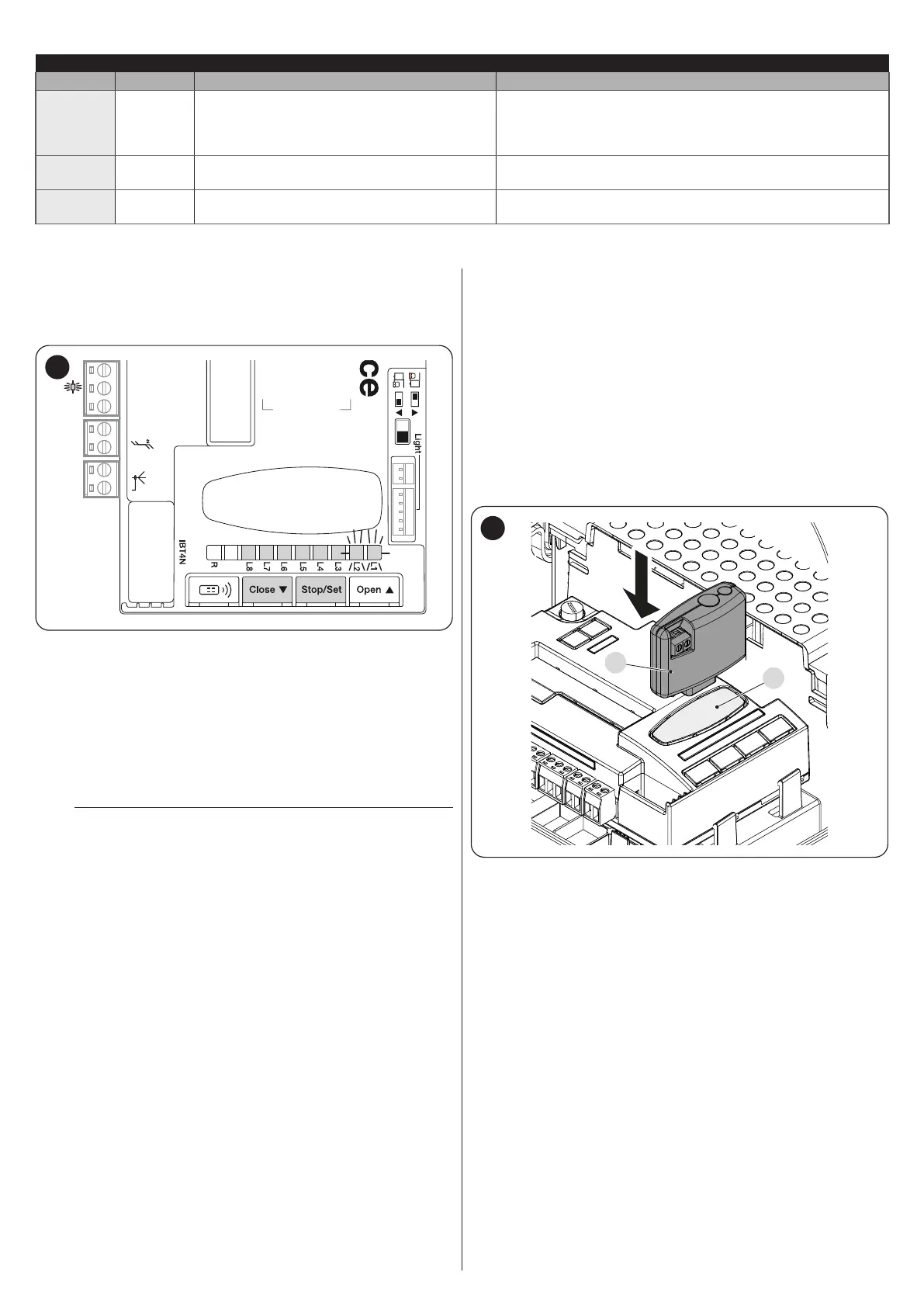
10.1.5 CONNECTING AN SM-TYPE RADIO RECEIVER
(OPTIONAL ACCESSORY)
The control unit has a slot for mounting radio receivers with SM connector
(optional accessories) belonging to the OXI, OXIBD, etc. families, which
can be used to remotely control the control unit through radio transmitters.
Before proceeding with the installation of a receiver, inhibit the operation
of the internal radio (refer to the paragraph “Level 1 programming (ON-
OFF)”) and disconnect the power supply to the control unit.
To install a receiver:“Figure 54”.
1. remove the pre-detachment element (A);
2. t the receiver (B) into the appropriate slot on the control unit circuit
board;
3. restart the control unit.
B
A
54
For the commands available and the memorisation modes, refer to the
modes relevant to the programming of the integrated radio receiver. (refer
to the “RADIO PROGRAMMING” chapter).
 Loading...


