3 - 9
3 Specifications
OMNUC G5-series (Pulse-train Input Type) AC Servomotors and Servo Drives User’s Manual
3-1 Servo Drive Specifications
3
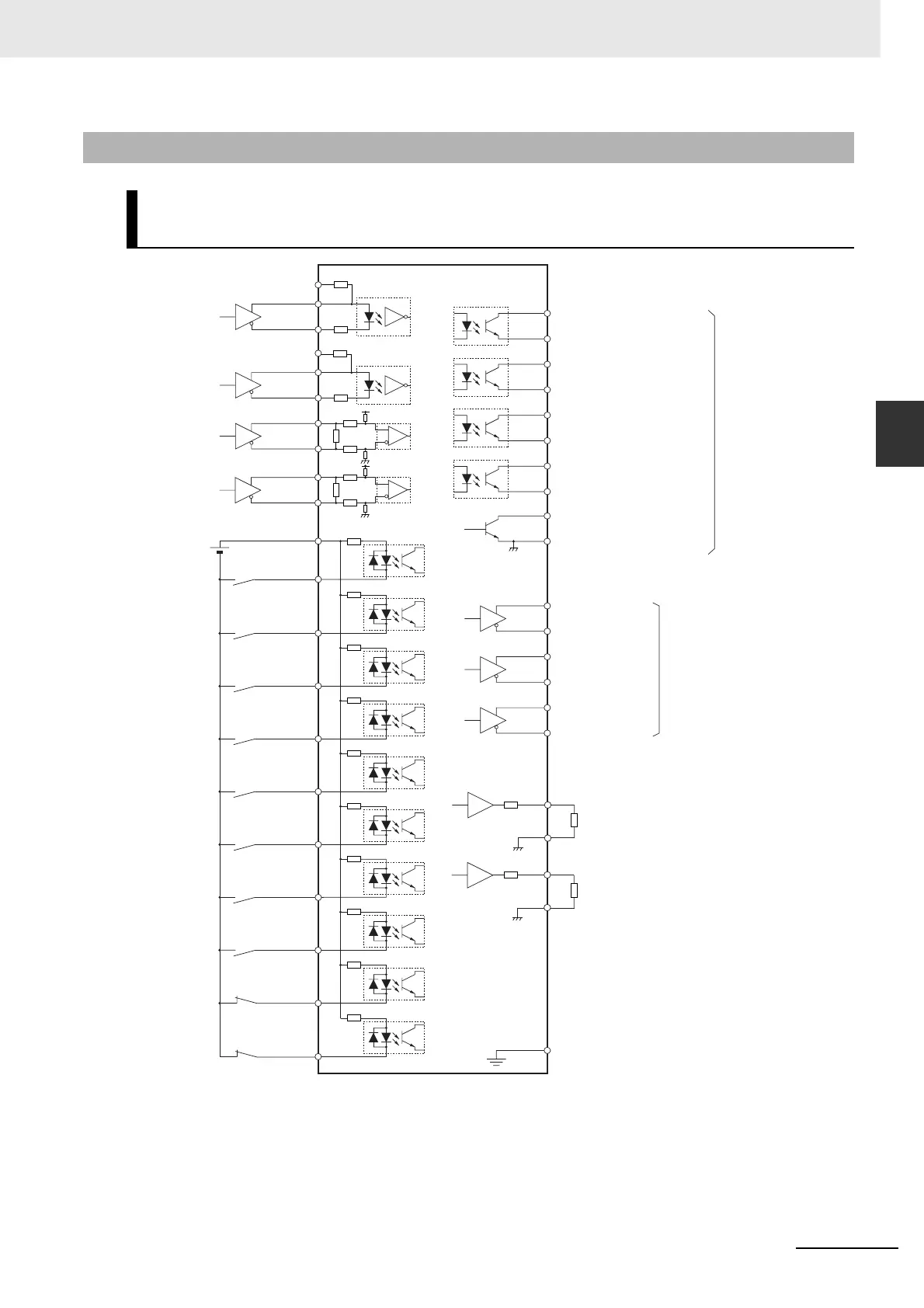
3-1-4 Control I/O Connector Specifications (CN1)
Note 1 The input signals to pins 8, 9, and 26 to 33 and the output signals to pins 10, 11, 34, 35, 38, and 39 can be
changed by parameter settings.
2 Use pin 25 (SGGND) to connect the GND wire if the pins 21, 22, 49, 48, 23, 24 are used for encoder
output.
3 It is not necessary to wire input pins that are not in use.
3-1-4 Control I/O Connector Specifications (CN1)
Control I/O Signal Connections and External Signal Processing
(Position Control)
3 kΩ
110 Ω
43 kΩ
3 kΩ
220 Ω
5
2
6
Operation
Command
44
45
+CW
–CW
+CCW
–CCW
+CWLD
–CWLD
Forward Pulse
Reverse Pulse
Reverse Pulse
Forward PulseForward Pulse
BKIR
Brake Interlock
Servo Ready Completed Output
Alarm Output
Positioning Completion Output
BKIRCOM
11
10
READY
READYCOM
ALMCOM
35
34
/ALM37
36
INPCOM
INP
39
38
32
TVSEL
31RESET
30ECRST
28GESEL1
27
GSEL
26
DFSEL1
29RUN
7
+24VIN
Control Mode
Switching
Alarm Reset
Error Counter
Reset
Electronic Gear
Switching
Gain Switching
Damping Filter
Switching
46
47
110 Ω
43 kΩ
33
IPG
Pulse Prohibition
4 Mpps max.
8NOT
Reverse Drive
Prohibition Input
9POT
Forward Drive
Prohibition Input
SGGND
Z
Phase-Z Output
(Open collector output)
19
25
Frame Ground
FG
50
4.7 kΩ
4.7 kΩ
4.7 kΩ
4.7 kΩ
43 kΩ
3 kΩ
+CCWLD
–CCWLD
+A
Encoder Phase-A
Output
Encoder Phase-B
Output
Encoder Phase-Z
Output
21
–A22
+B49
–B48
+Z23
–Z24
220 Ω
3
1
4
43 kΩ
3 kΩ
4.7 kΩ
4.7 kΩ
4.7 kΩ
4.7 kΩ
4.7 kΩ
4.7 kΩ
+24VCW
2.2 kΩ
+24VCCW
2.2 kΩ
1 kΩ
Analog Monitor
Output
42
43
13
15
1 kΩ
Line driver output
conforming to
the EIA RS 422A
(Load resistance:
120 Ω min.)
500 kpps max.
Maximum service
voltage: 30 VDC
Maximum output
current: 50 mADC
12 to 24 VDC

 Loading...


