7 Parameter Details
7 - 2
OMNUC G5-series (Pulse-train Input Type) AC Servomotors and Servo Drives User’s Manual
7-1 Basic Parameters
Explanation of Set Values
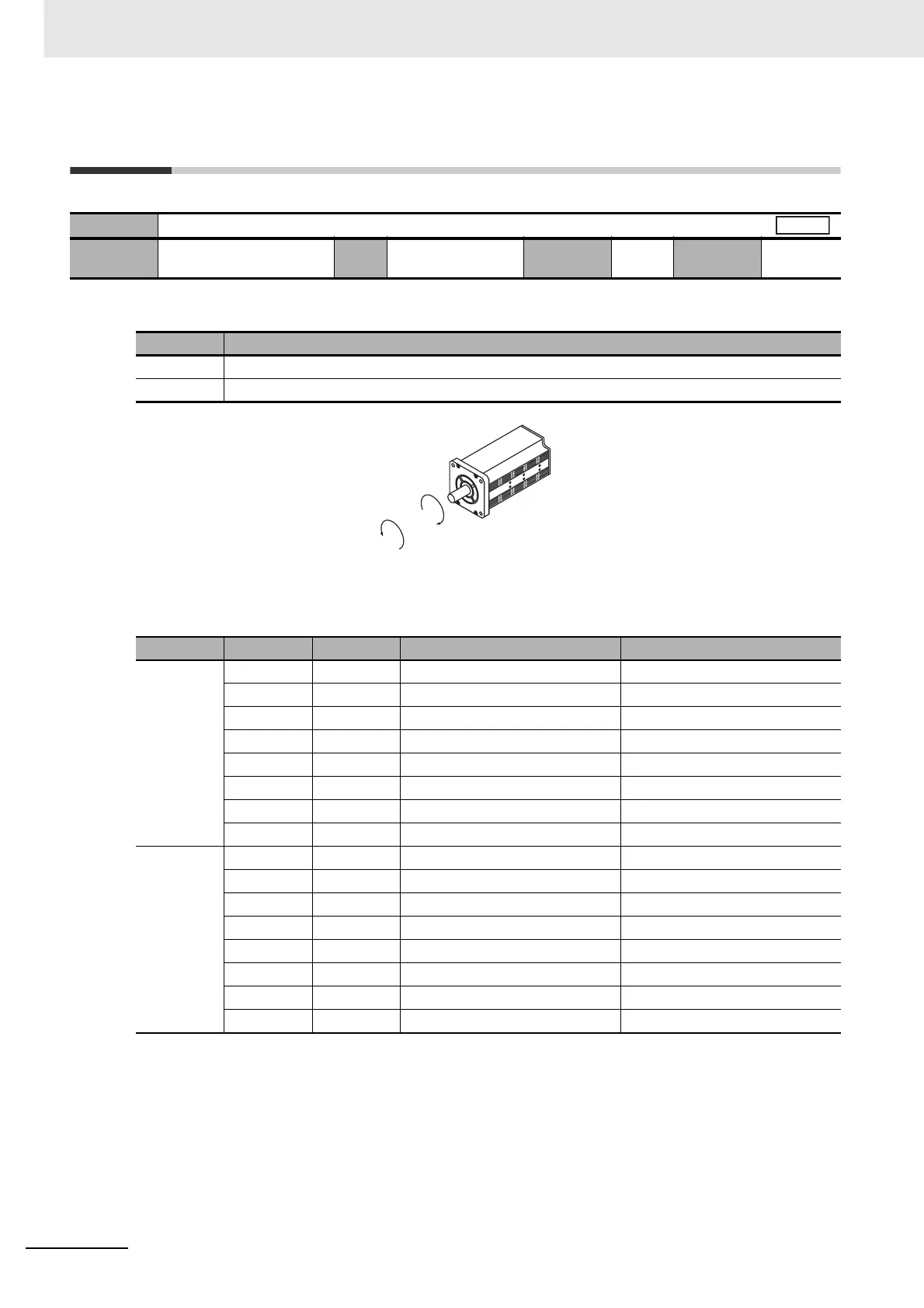
• Regarding the rotation direction of the Servomotor, a clockwise rotation is defined as CW and a
counterclockwise rotation is defined as CCW, when viewed from the load-side shaft.
The following table shows the motor rotation direction for the command.
Pn000
Rotation Direction Switching
Setting
range
0 to 1 Unit – Default
setting
1
Cycle the
power supply
Required
Set value Description
0 Forward direction command sets the motor rotation direction to CW.
1 Forward direction command sets the motor rotation direction to CCW.
Pn000 Pn006 Pn301 Command Servomotor rotation direction
0 0 – CCW pulse CCW: Forward
0 – CW pulse CW: Reverse
1 – CCW pulse CW: Reverse
1 – CW pulse CCW: Forward
– 0 Positive (+) internal speed CCW: Forward
– 0 Negative (–) internal speed CW: Reverse
– 1 Positive (+) internal speed CW: Reverse
– 1 Negative (–) internal speed CCW: Forward
1 0 – CCW pulse CW: Reverse
0 – CW pulse CCW: Forward
1 – CCW pulse CCW: Forward
1 – CW pulse CW: Reverse
– 0 Positive (+) internal speed CW: Reverse
– 0 Negative (–) internal speed CCW: Forward
– 1 Positive (+) internal speed CCW: Forward
– 1 Negative (–) internal speed CW: Reverse
All
CW
CCW

 Loading...


