3 Specifications
3 - 80
OMNUC G5-series (Pulse-train Input Type) AC Servomotors and Servo Drives User’s Manual
This connector is connected to the Servo Drive’s control I/O connector (CN1).
Use this connector when preparing a control cable by yourself.
For wiring methods, refer to Control Cable Specifications on page 3-84.
This connector is soldered.
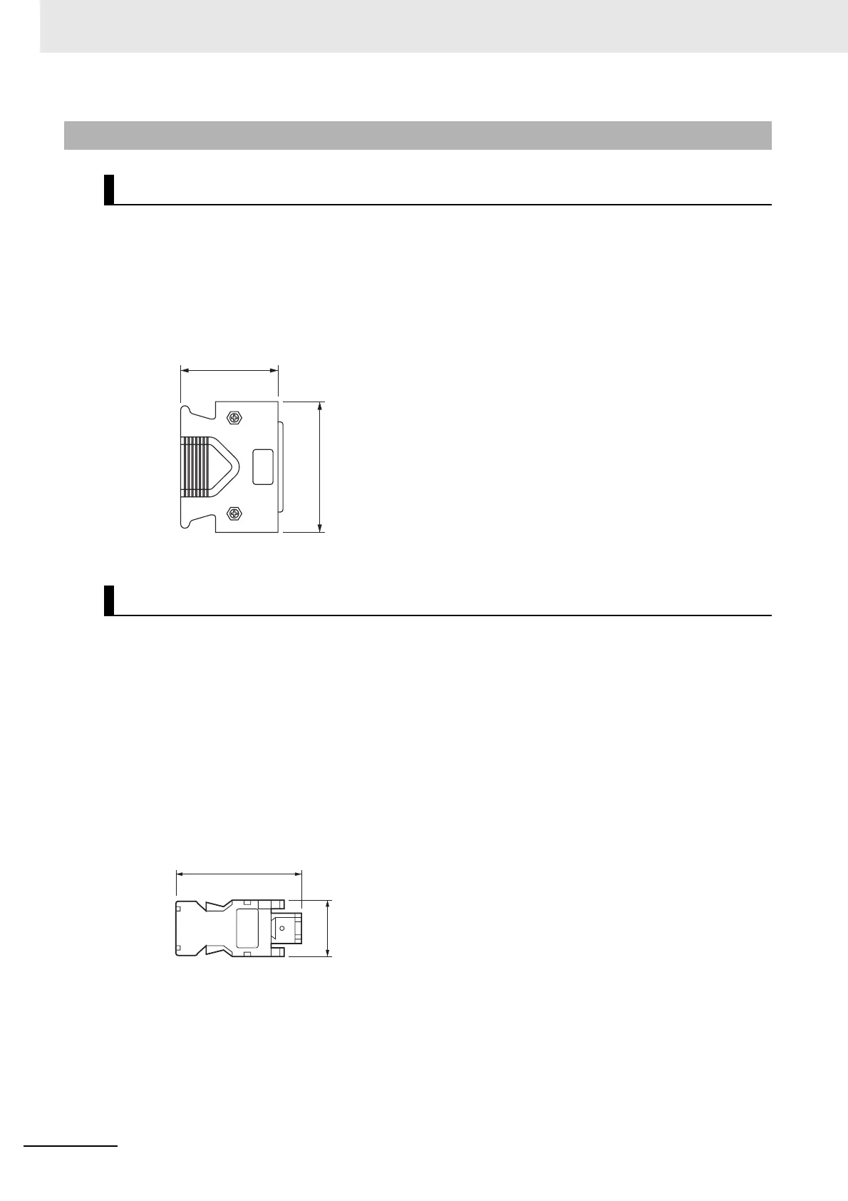
External Dimensions
These connectors are used for encoder cables.
Use them when preparing an encoder cable by yourself.
For wiring methods, refer to Encoder Cable Specifications on page 3-64.
External Dimensions
R88A-CNW01R (Drive’s CN2 side)
This connector is soldered.
3-5-4 Connector Specifications
Control I/O Connector (R88A-CNU11C)
Encoder Connectors
52.4
39
t = 18
Connector plug model
10150-3000PE (Sumitomo 3M)
Connector case model
10350-52A0-008 (Sumitomo 3M)
t = 12
43.5
18.8
Connector plug model
55100-0670 (Molex Japan)

 Loading...


